Stress Controller with Resistance Reinforcement
On the occasion of the Austrian Tunnel Day in Salzburg/A (please see report carried in one of the next issues of tunnel) the Porr Tunnelbau GmbH received one of 3 innovation prizes for the first use of the honeycomb stress control element with resistance reinforcement. This
prize is awarded for innovations of practical relevance. The application of this new
development is described in conjunction with the Tauern Tunnel.
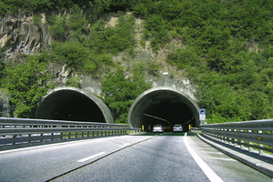
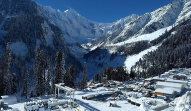
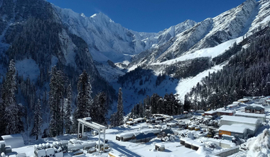
The Tauern Tunnel is part of the Tauern motorway from Salzburg to Villach/A. The first tube of the 6.4 km long tunnel was started in 1971 and completed in 1975 (Figs. 2 and 3). It is numbered among the busiest road tunnels in Austria. The Tauern Tunnel’s second tube has been under construction since July 2006, more than 30 years after the first one. The first round of blasting took place on Sept. 15th, 2006 and the second tube was broken through on July 8th, 2008 – after 22 months of driving. The 2nd tube is due to be open for traffic in June/July 2010. The Tauern Tunnel passes through phyllitic rocks with the exception of an approx. 400 m long rubble slope in the north. The cleavage planes run from north to northwest. The squeezing behaviour of the rock in the Tauern Tunnel was known from the excavation of the first tunnel tube. Stress controlling elements were foreseen at the planning stage in order to be able to accept the expected, protracted deformations without harm.
Purpose of the Stress Controllers
An important constructional element of the NATM is that the rock is used to help support the structure. Through the relaxation around the cavity the rock stresses are redistributed – so that a “rock bearing ring” is formed. Depending on the rock characteristics and the level of primary stress, considerable deformations can occur in the process, which in some cases can last for months on end. The shotcrete lining cannot accept major deformations of the rock without harm. Should there be major deformations these can cause spalling and in turn cause the shotcrete shell to be destroyed.
The stress controlling elements serve to support the rock, which split the ring-shaped shotcrete lining into segments and can bear the bulk of the deformations.
In this connection the working line of the stress controllers ideally lies just below the working line of the young shotcrete. As the deformation speed cannot be exactly calculated in advance, it is often hard to establish the optimal working line of the stress controlling elements from the very outset, Systems, which cater for a precise definition of the working line, can be applied more flexibly in this respect (Fig. 4).
Types of Stress Controllers, Developments and Findings
Deformation Slits
Originally deformation slits or diaphragms were installed in the shotcrete shell, which allowed movements and which were sprayed over once the deformations ceased. Good results were for instance obtained with this system in combination with strong anchors for the Inn Valley Tunnel. Owing to the open slits frequent cave-ins of the rock resulted as well as crumbling of the shotcrete.
Compressive Elements made of Steel
Compressive elements made of steel or of deformable materials (pore concrete etc.) were applied for safety reasons and in order to be able to use the shotcrete shell at an early stage as a supporting element. Two different systems are used in Austria.
M LSC elements are adjusted to the deformation behaviour of the rock convergences regarding type, number and length. This usually took place during the planning phase. An adjustment to the actual deformation behaviour on the spot is extremely difficult in the case of this system.
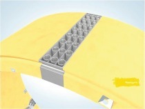
M The honeycomb stress controller known as “Wabe” produced by the Bochumer Eisenhütte Heintzmann GmbH & Co. KG is set up between load-distributing plates. It consists of flat-lying pieces of pipe with a defined pipe wall thickness and pipe diameter (Fig. 5).
The “Wabe” system allows forces to be accepted both in a tangential direction (normal force) as well as in a radial one (lateral force) as well as in an axial direction (longitudinal force in the direction of driving). The chosen load-path characteristics depend on the selection of the pipes that are used, i.e. they can be controlled via the dimensioning of the pipes (pipe diameter, pipe wall thickness, pipe section length as well as the choice of material and the steel quality). Through selecting different pipe combinations any desired load-path curves (from flat running to steeply rising) can be produced (Fig. 6).
The nature of the stress controlling elements makes it possible to adjust the load acceptance to the individual rock conditions. This takes place by placing further sections of pipe inside the existing ones (Fig. 7). The temporary hardening of the shotcrete is supported by the deformation capacity of the stress controller (deformation of the pipe sections) and in this way largely prevents cracks in the shotcrete shell.
As a result of the large number of combination possibilities regarding the pipe layers, the diameter and the wall thicknesses of the individual pipes as well as their number per layer a high degree of flexibility and the capacity to adjust to the rock conditions is the outcome. In this connection the normal force in the shotcrete shell increases continuously, i.e. uniformly. The working line possesses a continuous course. The way the pipes are set up and the fact that they are welded together with the load transference slats offer enhanced lateral stiffness and thus better lateral force transference in the deformation slit of the shotcrete shell. Through the proper choice of the types of pipe and the combination of the number of layers a more or less desired higher deformation path can be attained per stress controlling element.
Findings with Application in the Tauern Tunnel
The “Wabe” system was mainly used in the Tauern Tunnel and proved its worth. For contractual reasons (equivalence to the LSC system required at the bidding stage) the spatial dimensions as well as the load acceptance capacity had to be adjusted. The adjustment of the stiffness through the insertion of additional pipes was easily carried out and extremely effective.
Development Possibilities
Through the development of the flexible element further fields of application are conceivable. For example the system could be used as a yielding load distribution rail. This system can result in an improvement for connecting the bench or the floor especially in slightly squeezing rock should the ring closure have to be installed quickly for static reasons and the deformations last a long time given at the same time a high stress level.

