Zurich Weinberg Tunnel: All Drives forging ahead
An initial description of the contract sections 3.1 and 3.2 was published in tunnel 4/2008. The following report deals with further progress made by work on this important inner urban project.
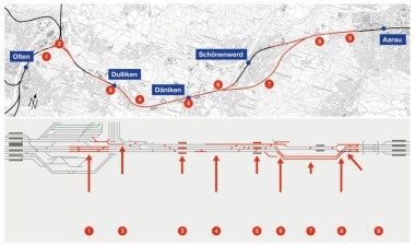
The execution of the construction scheme involves 3 local main aspects:
– the main drive from the Brunnenhof installation yard
– undercutting the south section of Zurich Central Station
– driving the escape and rescue tunnel from Oerlikon Station.
1 Main Drive from Brunnenhof
Since the start of construction enormous efforts have been undertaken at this point to ensure that the main drive got underway promptly. This endeavour has also succeeded. Only 13 months after construction began the TBM with a rump back-up was able to begin work in the start-up tube.
The prior condition for this was that first of all, the starting shaft with a depth of roughly40 m and 23 m in diameter was created. In addition the advance tunnel in the direction of Oerlikon had to be excavated as it is required to carry supplies during the construction phase.
1.1 Construction Procedure
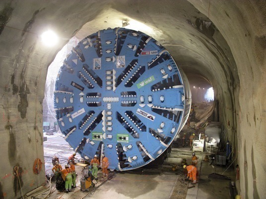
After these operations were concluded assembling the TBM and the first trailer could begun in July 2008. The individual segments of the body of the TBM were first put together in the shaft. The cutting wheel, which had previously been welded together on the installation yard, was subsequently lifted into the shaft and mounted on to the driving unit.
Given this set-up the shield body was moved laterally out of the shaft into the axis of the main tunnel, which as is presented in the first report, is located eccentrically to the shaft (Fig. 1). Towards this end steel brackets were welded on to the shield body, beneath which heavy-duty rollers were placed – after hydraulic jacks were used to raise it. With the help of these temporary undercarriages the shield was firstly moved laterally into the tunnel axis and then along the axis to the end of the start-up tube.
After the shield had been placed on the shield cradle, the trailers with the drive and supply aggregates had to be installed in the start-up tube and in the advance tunnel in the direction of Oerlikon. For this purpose a structure consisting of steel girders was set up to carry the back-up in the advance tunnel and the start-up tube. The trailers were mounted to the surface and lowered into the shaft by means of a mobile crane. The cross movement on to the roadway was executed with the aid of a mobile steel structure, which could be pushed into the roadway axis (Fig. 2).
The TBM and the rump back-up system began operating at the end of October 2008. By the time the Xmas break arrived 102 rings, 2 m in width, were installed. Molasse and mica sandstone had to be penetrated in the course of this section and the first buildings were undercut (including the DRS Radio-studio). The driving operations did not producer any settlements but showed, however, that the mica sandstone was more prone to wear than expected.
The second phase for setting up the driving installation began in January 2009. The trailers still lacking for installing the base invert and the carriage for laying pipes for the subsequent hydro section had to be added. In addition the material silos with the corresponding belt conveyors had to be installed in the advance tunnel and the concrete mixing plant set up on the surface next to the shaft head. This will supply the concrete for the floor and the tunnel’s inner vault. Furthermore the base concrete and the base fill for the section already driven had to be produced during breaks in driving (Fig. 3).
The listed jobs were to be carried out during the period up to March 23rd, 2009 in order to be in a position to commence with the high performance drive. Thanks to consistent work preparation and close pursuit of the ongoing operations this aim was attained. Since then driving operations have been taking place 5 days per week on a single-shift basis.
1.2 Penetrating the
Buchegg Rock Depression
The Buchegg rock depression was encountered roughly 240 m after resuming the TBM excavation. At this point the molasse field dipped down to tunnel roof level and even slightly below it and a bank of lime with a soft ground section above it consisting of ground moraine, glacial gravels and moraine appeared at tunnel roof level. The groundwater table in the gravels was then lowered thanks to wells to the level of the ground moraine. The depression extends over a length of some 210 m.
The rock depression was mastered without the driving method having to be modified, so that as a result a safety plan was projected in advance by the project compiler. Possible incidents were collected and assessed in this plan and the necessary standard, special and additional measures defined accordingly. Special equipment and material have to be made available by the contractor for these special and additional measures. This was decided on following consultations between the client, project compiler and the contractor. In addition a continuous operation for the rock depression phase was established in order to speed it up.
On April 20th, 2009, this tricky section was reached and the rock depression was overcome by the beginning of May without any difficulty. The TBM is now forging ahead under normal geological conditions and around 670 m of tunnel had been driven by the beginning of May 2009.
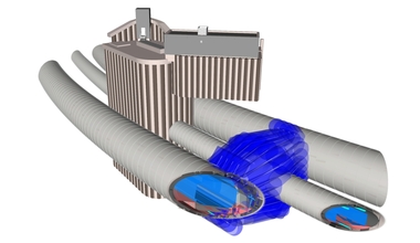
2 Undercutting the southern Section
Initially activities were characterised by the preparatory demolition and conversion operations for the Central Delivery Unit of Zurich Central Station and the Shop Ville, the stage-by-stage setting up of an ancillary bridge above the subsequent shaft (Fig. 4) in addition to the assembly as well as completion of the installations and the installation platforms. The actual construction work for the shaft could only be embarked on once these preparatory jobs had been accomplished.
The shaft serves various tasks at one and the same time and is thus split into two. Firstly the longitudinal heading and the tunnel beneath the southern section are produced from it and secondly the ancillary construction measures for the arrival of the main tunnel TBM (grouting the sealing block, large pipe umbrella) are undertaken.
On account of the local conditions the diaphragm walls for the shaft enclosure were created in 2 stages. Part 1 of the diaphragm walls (arched diaphragm wall at the TBM arrival side) was produced in July/August 2008. Part 2 for the remaining outer walls and the central wall was carried out from October to December 2008 after the head beam for the first part had been completed. The diaphragm walls were integrated in the molasse rock. Wagons were used to remove the excavated material from the walls. The desanding plant and the bentonite supply container were set up on the surface in front of the northern section of the station.
The work on the diaphragm walls had to be carried out under constricted conditions (Hmax = 5.75 m) (Fig. 5). The excavators could only be lowered into and raised out of the shaft by the rotary crane mounted alongside it as a result of which they had to be partly dismantled for this purpose.
After the diaphragm walls were created the 2 halves of the shaft were excavated and back-anchored – with different excavation levels being accomplished. The excavation height at the side of the longitudinal heading was roughly 2 m higher than at the side for the grouting block and the large pipe umbrella.
Then the first stage of the grouting operations for the target block was undertaken, i.e. the first 6 grouting rows were drilled and the sleeve pipes grouted with double packers. At the end of March 2009 this stage was completed and the installations for the first pipes for the large pipe umbrella set in the shaft. The first stage relates to the pipes Nos. 4, 2, 1, 3 i.e. all pipes, which lie above the roof of the main tunnel. They possess DN 1800 diameter. At the end of April 2009 the first pipe column with a length of 125 m was being driven.
The separation plant and bentonite supply container for grouting the pipes are situated roughly 300 m away from the point where the pipes are grouted, on a platform above the Limmat. They are set on wooden piles, which were rammed into the bed of the Limmat.
Simultaneously work on the first pipe umbrella stage for the northern and southern longitudinal headings was commenced below the southern section of Zurich Central Station (Fig. 6) in the other half of the shaft. Each pipe umbrella consists of 27 pipes 140 mm in diameter, which are installed extending from the wall sectors above the roof. Additionally above these pipes (in the roof) a further 10 pipes are installed in a parallel row to reinforce the roof segment. The centre distance between the pipes amounts to 30 cm in each case. Given pipe lengths of 14 m the useful driving length for driving the heading is restricted to 10 m. The pipe umbrella stages are installed alongside each other in the longitudinal direction of the heading with a sawtooth profile; as a result there is a 4 m overlap between the individual stages.
Twenty six 10 m long injection bore anchors are installed every 5 m to stabilise the face so that altogether 52 anchors reinforce the face.
At the beginning of May 2009 the first pipe umbrella sections in the northern and southern headings had been completed. The excavation of the southern heading had begun and had arrived at the end of the first pipe umbrella stage (Fig. 7). The second stage was under construction. Work on driving the northern heading can first be started when a stage has been excavated in the southern one.
3 Escape and Rescue Tunnel
During the execution phase the concept pertaining to the emergency exits and rescue headings was modified compared with what was originally projected at the tendering stage. The basis for this was the plan approval procedure dating from December 20th, 2006, as a result of which the gaps between the emergency exits in the central section of the Weinberg Tunnel were reduc-ed to some 500 m (originally 1,000 m).
Optimisation of the concept based on a proposal by the contractor, foresees the construction of an escape and rescue tunnel (FLRS) running parallel to the main tunnel, whose portal is located at the cutting at Oerlikon Station. The Tunnel Weinberg Consortium was commissioned to execute this solution.
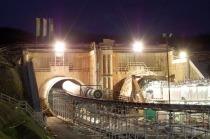
Following the conclusion of the planning work, construction on the spot started in April 2008 with the production of the pre-cut for the escape and rescue tunnel on the Oerlikon installation yard.
Once the pre-cut was produced driving operations for the heading began in mid-July 2008. The first metres were driven conventionally using a roadheader. The reason for this was the prevailing geology, which consisted of soft ground transforming to rock. This tunnel section possesses an approx. 20 m² cross-section and an ultimate length of 72 m. During the excavation phase the muck was removed and transferred on to trains by means of a wheel loader.
Parallel to driving the first metres of the heading the gripper-TBM with back-up components was assembled for the subsequent mechanised excavation in molasse. The TBM possesses a boring diameter of 4.75 m. Once assembly was concluded the TBM was able to move into the advance tunnel. Driving operations commenced at the end of September 2008 and are currently still in progress. The section to be tunnelled is 4,387 m long and finishes up at the lowest point of the main tunnel. From there the FLRS will be directed to the surface by means of a 542 m long roadheader drive emerging into the open at the Seilergraben (Fig. 8).
The first bored metres up until approx. TM 450 were characterised by ingressing water, cave-ins of up to around 1.5 m and associated complex supporting measures. This was caused by the location of the roof of the heading in the rock zone with instable conditions. It was further propagated by the bedded structure of the fresh water molasse given the horizontal formation of the series of strata. The geological conditions markedly improved after TM 450 so that subsequently the rates of advance that were strived for were attained or even exceeded. The rates have ranged from 110 to 132 m/week for weeks on end given a daily best performance of 31.5 m/16 h.
The cavity is secured using shotcrete (d = 12 cm), a layer of netting and friction anchors
(I = 2.4 m) backed up by UNP profiles (Fig. 9).
As of at the beginning of May 2009, approx. 2,000 m of the heading had been accomplished, representing around 45 % of the total length.
The muck is removed by train via the bunker silos and the material loading unit to the Oerlikon installation yard. Towards this end the material transport belt from the heading is linked with an underground cross-belt and an ascending belt to the bunker silos of the main tunnel excavation.
4 Logistics System in Oerlikon
The logistics system in Oerlikon has been set up and all its components have been functioning since the end of March 2009. The following units are involved:
On the west side of Oerlikon Station
– discharge channel for gravel.
On the east side of the station
– bunker silos for muck from the main tunnel and the FLRS muck loading unit
– material delivery for muck from the FLRS
– belt conveyor system to connect the individual components with the drives (Fig. 10).
The system was built up in sections in keeping with the requirements of the drives. In some cases the installation work could only be accomplished (above all in conjunction with the tracks) during the night as tracks had to be closed down. Bulk goods are able to be transported to and from the project by means of this system.
Concrete aggregate is carried via a belt bridge above the tracks at Oerlikon and further through the advance tunnel to the shaft bottom at the Brunnenhof installation yard. There an elevator caters for its further transport to the surface to the bunkers for the concrete mixing plant.
The storage containers for the bulk material, which are set up in the advance tunnel, are supplied by means of the same belt system. Towards this end the main belt transfers the bulk material (all-in gravel , drainage gravel and pearl gravel) to a distributor belt, which is located above the silos so that it can fill them individually. The storage containers are emptied via a discharge belt, which is located underneath. This discharge belt directly loads the transport vehicles in the tunnel.
A separate belt runs from the TBM through the advance tunnel up to the bunker silos in Oerlikon. This is used to remove the tunnel muck. It is further transported from the bunker silos to the loading unit and to rail wagons.
5 Segment Production
A 5-part segmental ring with a keystone located at its base is used for lining the tunnel. 3 different types of segmental rings have to be produced for the project: Types A and B for the molasse section of the excavation and Type C for the hydro section. These types relate to the different sealing systems to be found in various sections of the tunnel at the roughwork stage and to the driving system.
The difference between Types A and B lies in the thickness of the base segments. In the case of Type B the base segments are reinforced and 60 cm thick, whereas all Type A segments are 30 cm thick. Both types are expanding segmental rings, which are used for the molasse rock.
Type C is basically different from the other 2. It is constructed to be watertight and thus fitted with a rubber seal. It is also 30 cm thick, consists of 5 parts plus a keystone at the top. Left-hand and right-hand rings are planned.
All the segments are 2 m wide. Around 2,200 rings have to be produced for the tunnel excavation. Production of the segments is located in Wilchingen. A prefabricated part plant has been set up there, comprising a production hall and an open area for storing the segments. Producing one’s own pre-cast parts emerged as the most economically favourable solution.
The segments are produced on a carousel system using the thermal reflux method. Type 1 formwork, which can be modified, has been devised for segment types A and B. There are 3 formwork sets consisting of 5 units each as well as 3 keystone units, which are used 3 times daily during a 2-shift operation. In this way 225 segments can be produced per week during a 5-day set-up. Currently Type B segments are being produced but after this series is completed, Type A will be tackled following the necessary modification work. Type C will then be embarked on at the end of the production period.
The segments are transported by lorry from the external yard to the Brunnenhof installation yard in Zurich.
6 Outlook
Currently all drives are in progress relating to section 3 of the Weinberg Tunnel project. The construction programme foresees that the escape and rescue tunnel will be completed first. This is scheduled for the end of October 2009. The gripper-TBM will largely have been dismantled by the end of 2009.
The main tunnel drive will reach the end of the molasse section as scheduled in spring 2010. Only then will it be possible to convert the system to hydro mode and then tunnel the remaining 246 m to the southern section shaft.
The drives for the longitudinal heading will last until the end of 2009 so that the work on the diaphragm walls can be launched from it.