2nd Main Line Munich: Drilling Technology for Compensation Grouting Around Marienhof Station
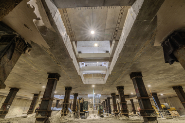
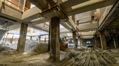
The central access structure to the new Marienhof Station on the 2nd S-Bahn Main Line is being built using the diaphragm wall/top-down construction method. With five bracing levels and a depth of 42 m, this will be the deepest excavation pit in the centre of Munich. From the excavation pit at Marienhof, the platform tubes of the station and a connecting tunnel to the existing U3/U6 underground railway line are being driven under compressed air. To secure the buildings and to mitigate possible settlements, the buildings and the existing tunnels above the platform tubes to be constructed, are bolstered with a compensation grouting screen.
1 Scope of the Compensation Grouting Work
Sensitive existing buildings and tunnels are located within the area of influence of the platform tunnels to be constructed. To the east of the excavation pit lies the imperial residence “Alter Hof”, Munich’s oldest building complex. There are also numerous high-value buildings around the Marienhof. The existing tunnels of the U3/U6 subway line run in close proximity to the access structure and at a short vertical distance from the platform tunnels to be constructed; these tunnels will continue to be used under normal operating conditions throughout the construction period. These sensitive existing structures are being closely monitored using measurement technology to control their deformation behaviour. Compensation grouting is intended to prevent harmful deformations of the building structure. The extent of the compensation grouting is shown in Figure 1.
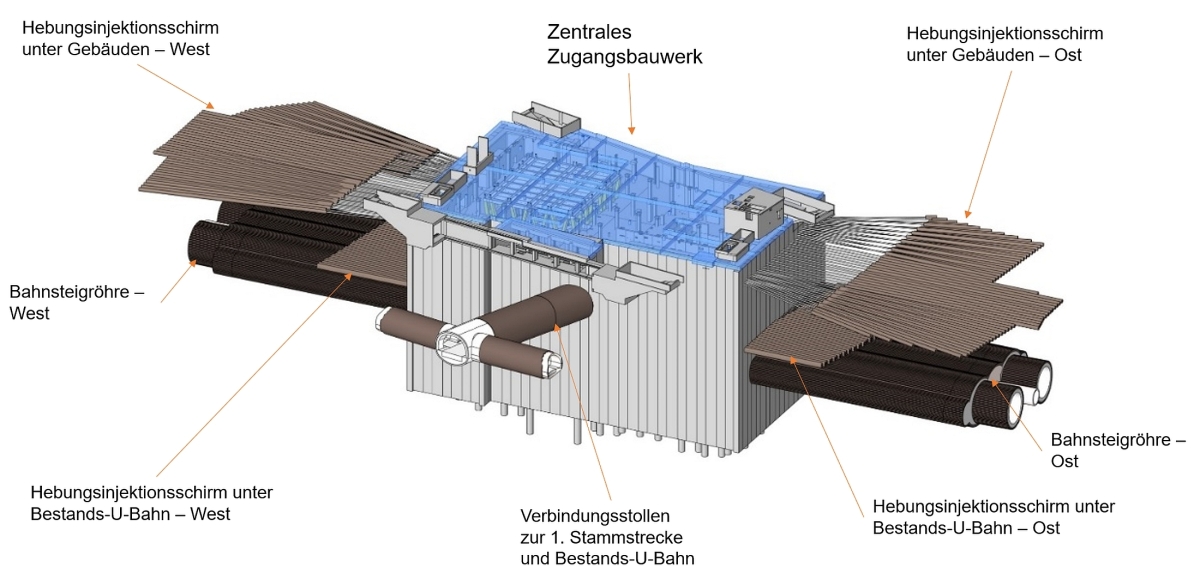 1 | Entrance structure to the new Marienhof Station with platform tunnels, the connecting tunnel and the compensation grouting screens
Credit/Quelle: ARGE Marienhof
1.1 Compensation Grouting ScreenBeneath the Buildings
As the entire settlement depression is very large, but incompatible deformations occur only in certain areas, the required screen dimensions were determined using complex modelling calculations. The compensation grouting screens consist of steel pipes driven into the ground as parallel and as close to horizontal as possible, which feature check valves at intervals of 0.5 m and are referred to as sleeve pipes due to the external rubber sleeves. Using a so-called double inflatable packer, which is inserted into the sleeve pipe up to the desired injection point, the sleeve pipe can be sealed off in front of and behind the corresponding check valve. This ensures that the grouting material, which is fed via a high-pressure hose attached to the double inflatable packer, can only enter the ground at this single injection point (Fig. 2). At the end of the pumping process, the check valve’s sleeve immediately seals against the outside of the sleeve pipe, preventing the grout from flowing back into the sleeve pipe.
 2 | Sleeve pipe and double inflatable packer
Credit/Quelle: ARGE Marienhof
The grouting parameters are tailored to the subsoil in such a way that the soil structure is fractured. In accordance with the prevailing stresses in the soil, predominantly vertical cracks are formed initially, causing the stresses in the subsoil to redistribute in a mainly horizontal direction. Eventually, cracks form that are predominantly horizontal, enabling uplift that can be controlled quite precisely in terms of both location and magnitude. Up to this point, the process is referred to as “preparatory grouting”; beyond this point, it is referred to as “compensation grouting.”
Due to borehole lengths of up to 105 m and the very tight construction tolerance of 0.5% of the borehole length, the boreholes required for installing the sleeve pipes are created using directional drilling with continuous borehole support.
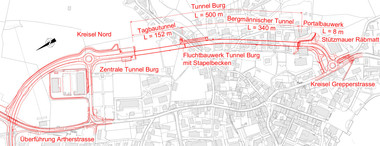
 3 | Site plan showing the grouting screen beneath the buildings and the first test area outlined in red
Credit/Quelle: ARGE Marienhof
 4 | Detail from the 3D model of the excavation pit (Captions from top to bottom: building view from below, well gallery, shallow foundation with compensation grouting screen, depth measurement point, deep foundation with compensation grouting screen)
Credit/Quelle: ARGE Marienhof
Their elevation varies between approximately 7 and 16 m below ground level and depends on the building foundation to be penetrated. Since the reinforcement of the existing diaphragm wall may only be drilled through to a limited extent for structural reasons, the drilling starting points must be grouped into vertical sets of three, the “drilling lanes,” and fanned out laterally from there. The endpoints of these three-point fans then lie roughly at the same elevation. The location of the compensation grouting screens is shown in Figure 3; the first test grouting field that was carried out is outlined in red there.
An additional challenge is posed by the confined space within the excavation pit, which is characterized by temporary supports located approximately 6 m from the wall, as well as numerous wells, monitoring points, and deformation measurement devices. To relieve stress on the
excavation pit enclosure and the compressed air tunnelling process, external groundwater lowering is required in addition to internal measures. The well field, along with depth measurement points for ground deformation and existing wells, complicates the drilling process. Figure 4 shows a section of the 3D model outside the excavation pit, which gives an impression of the density of structures in the ground. In total, approximately 19 km of sleeve pipes will be installed via directional drilling to raise the existing buildings.
1.2 Compensation Grouting Screen Beneath the Existing Underground Railway
 5 | Layout of the grouting screens (red) to the west of the access structure
Credit/Quelle: ARGE Marienhof
The existing tunnels of the U3/U6 underground line run parallel to the diaphragm wall at a short distance to the east and west of the Marienhof excavation pit. Beneath each of these tunnels, an additional compensation grouting screen will be constructed, albeit significantly smaller in size. The screens consist of 132 sleeve pipes with a total length of approximately 3.2 km, as well as 12 horizontal inclinometers for monitoring ground movements between the grouting screen and the subway tunnels.
Figure 5 shows the arrangement of the grouting screens relative to the existing structures and ground excavation, using the western side of the excavation pit as an example.
1.3 Current Status of Works
The boreholes for the compensation grouting beneath the buildings were drilled in February 2023. The drilling work from levels -1, approximately 7.7 m below ground level, and -2, approximately 14.6 m below ground level, was successfully completed in autumn 2025. This involved a total of 256 boreholes with a total length of approx. 19.3 km.
In spring 2024, grouting was carried out in an initial test field comprising eight boreholes beneath the shallow foundations of the western buildings, followed in autumn 2025 by a further test field beneath the shallow foundations of the eastern buildings, and in spring 2026 the test grouting beneath the buildings was successfully completed with a test field beneath the deep foundation of the western building block, the “Schäfflerblock”. The results form an important basis for the compensation grouting to be carried out later. The preparatory grouting beneath the shallow foundations of the western buildings commenced in spring 2026.
2 Geology
 6 | Geological cross-section (west-east) of the new access structure [2] (fill = white; quaternary gravels = yellow; tertiary clays/silt = purple; tertiary sands = orange; compensation grouting screens = green lines)
Credit/Quelle: ARGE Marienhof
The Quaternary gravels and sands shown in yellow in Figure 6 are overlain by fills of varying thickness (white). Beneath this lies a Tertiary interbedded sequence of semi-consolidated to consolidated, silty clays (aquitards, purple) and densely consolidated, silty sands (aquifers, orange), which are intermixed in a lenticular fashion in places. The sands may be locally cemented by calcite to form a light sandstone. The clays exhibit zones locally consolidated into claystone.
3 Creation of the Grouting Screens
3.1 Drilling System
 7 | Modified Bohrtec BM 600 LS jacking machine
Credit/Quelle: ARGE Marienhof
The boreholes in the fill and the Tertiary strata are constructed using a guided drilling method based on the double pilot drilling technique, as this combines the highest possible drilling accuracy of all currently available methods with optimum process reliability under the given conditions. A modified Bohrtec BM 600 LS long frame jacking machine is used for this purpose. Figure 7 shows the machine in a deep drilling position. It can “climb” hydraulically to a height of up to 9 m (drilling axis), a feature utilised on the east side of the excavation pit. The jacking machine and lifting frame have been adapted to the confined space and are available in two versions (long and short). Switching between versions is possible on site at any time.
A system from the pipe jacking sector, which has been tried and tested for decades, is used to align the drill head; this is supplied unchanged by the drilling rig manufacturer. It operates optically using a theodolite camera, which captures an image of a diode target plate in the control head and displays the video feed in real time on a monitor for the rig operator. The theodolite’s target axis represents the intended drilling axis. Deviations from this highly accurate reference are immediately apparent to the rig operator with a resolution of just a few millimetres. Furthermore, this system gives the rig operator a good understanding of how the steering head operates. For example, obstacles are immediately noticeable through an ‘uneven’ motion, allowing for an early response. No other steering system offers such high accuracy and information density whilst simultaneously providing maximum
operational reliability and resilience. To navigate around any larger obstacles, a highly accurate and long-term stable inertial probe can be used, which can be inserted into the inner string and locked in place behind the steering head. From there, it continuously transmits its deviation from the target borehole axis and its spatial orientation to the rig operator in real time (“Measurement whilst drilling – MWD”. This system was developed by JV partner Implenia for ground freezing drilling in Berlin and offers outstanding accuracy and reliability for this class of positioning systems.
3.2 Installation of the Sleeve Pipes
For geological reasons, the boreholes are drilled using rotary flushing with a bentonite circulation fluid. Due to the external groundwater level reduction, the counterpressure is only a few metres of water column. The drilling system, originally designed to construct freezing lances in Berlin sand and marl, has been further developed accordingly.
In addition to the casing carried down the borehole, this system applies a constant supporting pressure to the borehole wall via the bentonite-based drilling fluid, which corresponds to a water column of several metres above the external groundwater table. After the installation of the sleeve pipes, the drilling fluid is replaced air-free by a hardening suspension with low settling rate, known as the “casing mixture”. During this process and the subsequent removal of the drilling casing, the support pressure is maintained by means of a four-stage preventer specially adapted to this drilling system. Only the sleeve pipe embedded in the casing mixture and the steering head of the directional drilling string remain in the ground.
To ensure that the sleeve pipes can be cleaned effectively during grouting operations whilst using a minimum amount of flushing water, the boreholes are inclined at an upward angle of approximately 1%. As the air contained within the drill pipe cannot be displaced into the tightly packed ground, the drill pipe is carefully vented before the grout mixture is pumped into the annular gap between the drill pipe and the rock. In this final step before the steering head is disconnected, the drilling fluid is displaced from the annular gap and discharged under pressure through the preventer and standpipe. After the steering head is disconnected, the outer drill pipe is withdrawn, leaving only the steel volume of the drill pipe itself to be replaced by the casing mixture.
 8 | Illustration of the ratio between the sleeve pipe (black inner circle) and the bore diameter (blue)
Credit/Quelle: ARGE Marienhof
The diameter of the specified sleeve pipes and the borehole diameter required for directional drilling resulted in a significantly larger annular gap for the casing mixture compared to the standard dimension (Fig. 8). This had been taken into account during the preparation of the boreholes through an appropriate selection of the casing mixture. The aim was to achieve brittle material behaviour with low uniaxial compressive strength to obtain a stable breach in the casing mixture even at lower burst pressures.
3.3 Experience Gained During theDrilling Operations
The drilling system proved well suited to the obstacle-free sections of the geology described above. The borehole maintains a straight course very well in these strata, and the installation of the sleeve pipes proceeds without any problems throughout. It also provides a stable basis for dealing with previously unknown disruptions. The latter were particularly evident on the western side at level -1 in the form of fluid loss. Flowcharts (so-called “action guidelines”) drawn up in collaboration with the client and the associated institutes helped the drilling team and the site supervision to respond quickly and successfully, even during 24-hour operations. The principle and aim of these action guidelines was to seal the open structures in the subsoil with high-viscosity filler before the sleeve pipe was embedded in the casing mix.
Using modified drill bits, hard inclusions in the axis could be drilled through (masonry, lean concrete) or cored (steel girders, concrete, sandstone). The latter occurs more frequently on the east side.
The pressure-retaining installation of the sleeve pipes was consistently very successful, apart from phases of significant flushing losses caused by the ground conditions. Drilling-induced settlement of the existing buildings was insignificant within the context of general construction-related settlement. Overall settlement to date is well below the forecast.
3.4 Sustainability Aspects
 9 | Comparison of cement consumption in jet grouting (22 000 t cement; left) and compensation grouting (50 t cement; right) [1]
Credit/Quelle: ARGE Marienhof
 10 | Mass balance of soil disposal
Credit/Quelle: ARGE Marienhof
 11 | Drilling fluid circulation and fluid treatment
Credit/Quelle: ARGE Marienhof
Compensation grouting is not only a minimally invasive method for stabilising buildings, but also offers advantages over other methods in terms of sustainability and carbon footprint (Fig. 9, [1]).
Here, this aspect has been further enhanced through optimisations in the fluid circuits, as the disposal of suspensions and thin sludge in the vacuum truck is, on the one hand, problematic in terms of landfill management and, on the other hand, offers significant potential for CO2 savings. Consequently, the circulating drilling fluid is not only desanded but also cleaned using high-performance centrifuges, thereby significantly extending its service life.
Just like the drilling fluid, the cleaning wastewater that accumulates under the cover is treated using a centrifuge and largely reused for flushing the sleeve pipes and for mixing new drilling fluid. The solids it contains are removed in dry form. This sector produces around 80 tonnes of thin sludge per month. Of this, around 30 tonnes of solids are already screened out in the desander and disposed of in open hoppers. The remaining approx. 50 tonnes of fine slurry contain a solids load of approx. 10 tonnes, which is separated by the centrifuge and also disposed of in open hoppers. Figure 10 illustrates the proportions.
A twin-centrifuge system is used to ensure that both processes can run independently. To cover peak demand, both centrifuges can also be operated in parallel (Fig. 11).
In addition, the consumption of cement-containing fresh slurry was reduced by approximately 24% through separate storage and reuse of the casing mixture during pipe pulling. In this process step, approximately 20 litres of clean casing mixture, which is still well within its pot life, are released for every metre of outer pipe pulled. This is no longer discarded, but is collected in a separate mixing vessel and returned to the backfilling process using a pump specially configured for this purpose.
4 Grouting in the Test Area
Figure 12 shows the test area in relation to the load-bearing structure of the selected building. It is situated within the compensation grouting screen for the tunnelling works at the corner of a building with shallow foundations. On its western boundary, it adjoins a building with deep foundations.
4.1 Objective
 12 | Top view of the first test field (outlined in red)
Credit/Quelle: ARGE Marienhof
 13 | Overview of the second and third cycles of preparatory grouting (second cycle = blue, third cycle = orange)
Credit/Quelle: ARGE Marienhof
 14 | Overview of the compensation grouting phases
Credit/Quelle: ARGE Marienhof
The aim of the test grouting was to obtain parameters for the design of the subsequent lifting operations accompanying the tunnelling and for the design of possible preliminary lifting. Furthermore, the fracturing behaviour of the thick-walled grout mixture and the general soil reaction were to be tested. Another important aspect was the influence of the open structures in the ground that were backfilled during the drilling work.
4.2 Conduct of the First Grouting Tests
4.2.1 Preparatory Grouting
First, preparatory grouting was carried out across the entire area with a target lift of 1–2 mm. To this end, every second valve across the entire test area was injected with a filler slurry (RoV 5004 with a water-solids ratio w/s = 0.8). In two further rounds, sub-areas that had shown a lower response were grouted again (Fig. 13). This time, the individual volumes per valve were reduced from 20 litres to 10 litres.
4.2.2 Compensation Grouting
The requirement for the lifting test was to achieve levels of lifting that were significantly below the predicted settlement for this area, whilst ensuring that the angular distortions in the building that had developed previously were not exacerbated. Consequently, in close consultation with the client, a maximum lifting target of 5 mm was set, including preparatory grouting in the south-east corner, tapering off towards the north and west.
To this end, in accordance with the tried-and-tested principle of “from deep to high”, four grouting passes were carried out with progressively decreasing individual volumes down to 5 litres per valve, as shown in Figure 14.
4.3 Findings From the Test Area
 15 | Relationship between injected volumes and the resulting elevations (orange line = hose scale reading, blue line = cumulative grouting volume [l])
Credit/Quelle: ARGE Marienhof
As can be seen in Figure 15, the preparatory grouting (first rise in the red graph, left) produced a steady uplift response at an early stage, with only minor declines in uplift after the grouting was completed. Following compensation grouting (second major rise in the red graph, right), there were virtually no further downward movements of the building. In particular, no subsequent migration of grout into neighbouring areas or grout leakage onto the surface or into buildings or sewers was observed.
The uplift efficiency – that is, the ratio of the actual uplift measured by a sensor to the theoretical uplift of a hydraulic cylinder for the same area-based grouting volume – naturally varied greatly across the surface of the test area. Particularly at the western edge, towards the neighbouring house with deep foundations, the efficiency, as expected, approached zero. Otherwise, the efficiency values for preparatoty grouting ranged between 7 and 11%, and for compensation grouting between 9 and 31%.
Generally, the grouting pressure rises sharply at first after the pump is switched on, until the casing mixture ruptures and the grouting material can begin to penetrate the ground. The highest point of this pressure peak is usually referred to as the ‘burst pressure’ or ‘rupture pressure’. The grouting pressure then usually drops sharply again, whilst the flow rate rises to or near the target pump rate. The temporal progression of the grouting pressure at a constant pump rate provides qualitative information about the interaction between the soil and the grouting material.
 16 | Example of a valve‘s pressure-flow diagram (green line = pressure [bar], blue line = flow rate [l/min])
Credit/Quelle: ARGE Marienhof
The time-dependent pressure and flow curves of the individual grout injections mostly showed moderate burst pressures of around 15–20 bar, followed by a fairly constant pressure curve, which suggests uniform opening of the uplift cracks in the ground without excessive displacement of water from the grout (Fig. 16).
At a few valves, higher burst pressures of up to approx. 50 bar were also observed. In isolated cases, it was not possible to burst the valves. These valves were located almost exclusively in areas that had been backfilled with filler at the time of drilling to counteract flushing losses that had occurred there. The low frequency and distribution of these outliers do not require any change in drilling procedures for zones of higher permeability.
5 Summary and Outlook
Given the heterogeneous build quality and foundation conditions of the existing buildings, their cultural and economic value, and their high-quality use, the requirements for damage minimisation set out in the planning approval are very stringent.
Compensation grouting is therefore of great importance as an accompanying measure in this complex project. Furthermore, the given constraints require a particularly sensitive approach to the existing buildings.
The casing mixture, specially tailored to its large wall thickness, met the expectations placed upon it well. It could be fractured directly with grout at moderate pressures. The selected grout is well suited to the existing ground. It remained stable within the settlement crack and was easily pumpable. There was no migration or drainage into open structures. The backfilling of these voids carried out during drilling was successful. The ground responded well in all test areas, although there were marked differences to the test area beneath the shallow foundations of the western buildings, particularly to the east of the excavation pit. The preparatory grouting lof the pile foundation for the Schäfflerblock was very straightforward and easily controlled. Further test grouting is still pending beneath the existing tunnel tubes of the U3/U6 underground line, which will commence this early summer.