An Extraordinary Process: Immersed Tunnel for Weser Crossing Near Bremen
In order to improve the traffic situation in north-western Germany and the connection to the international motorway network for the freight transport centre, port and airport, the A281 near Bremen is currently being expanded. Here, the remaining gap in the highly frequented ring motorway, the western corner connection between the A1 and A27, is being closed with an immersed tunnel in the Weser. The following article presents this unusual tunnel project with its particular characteristics and provides an overview of the current status of the work.
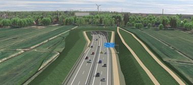
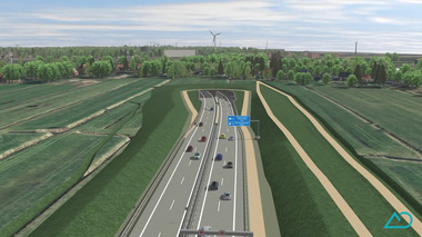
 1 | The centrepiece of the A281 link road near Bremen is the almost 1.1 km long immersed tunnel in the Weser river
Credit/Quelle: Wayss & Freytag
The crossing beneath the Weser river, which closes the gap in the A281 between the A1 and A27 motorways, is an important project that will relieve congestion on both motorways and on the access roads to the Hanseatic city of Bremen. The project was awarded by DEGES (Deutsche Einheit Fernstraßenplanungs- und -bau GmbH) on behalf of Autobahn GmbH des Bundes to Wayss & Freytag Ingenieurbau AG. It comprises the construction of the approximately 4.8 km long, four-lane motorway route, including the Weser crossing with an approximately 1.1 km long immersed tunnel (Fig. 1). The parallel construction of two immersed elements in an external dry dock will save around two years of construction time. Work began in the summer of 2023, and the south-western corner connection is scheduled to go into operation in 2030.
1 Project Description and Characteristics
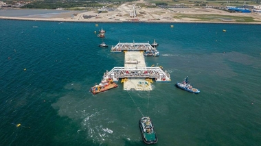
One of the last two sections of the A281 motorway still to be built is located between the existing junctions at Seehausen in the south and Gröpelingen in the north of Bremen. The centrepiece of the new motorway route is the immersed tunnel crossing the Weser river. The six tunnel elements are being constructed in a dry dock in Bremerhaven, towed on the Weser to the construction site some 60 km away (Fig. 2) and, after temporary storage in Bremen‘s industrial port, lowered into the excavated channel in the Weser.
 2 | A total of six tunnel elements are being constructed in a dry dock in Bremerhaven and towed on the river Weser to the construction site some 60 km away
Credit/Quelle: Eric Shambroom Photography
Particular attention is being paid to flood protection, as the excavation pits on both sides of the Weser are affected by the tide. Since the existing flood protection wall on the north side and the dyke on the south side have to be opened for the work, flood protection will be installed on the shoring walls and around the sinking excavation pits.
The following services, among others, will be provided:
Explosive ordnance detection and recovery in the tunnel area and in the Weser
Constructing the excavation pits for troughs, immersed concrete elements and cut and cover tunnel construction in sections on the north and south sides
Construction of a protective gallery in the area of the slag tip of the Arcelor Mittal Bremen steelworks (AMB)
Trough structures for the north and south sides adjacent to the tunnel structures
Tunnel sections in the northern and southern areas using cut and cover
Construction of the immersed tunnel including dredging work for the trench in the Weser river
Construction of the final joint
Construction of the operations buildings on the north and south sides
Road construction along the entire length
Landscaping
The logistical challenge arises from the production of the concrete elements in Bremerhaven, the towing process to Bremen for temporary storage and the actual lowering into the Weser. Added to this are particular characteristics such as the tidal range of the Weser of approximately 4 m in Bremen, the changing flow directions and speeds, shipping traffic, dredging work for the trench in the Weser and the up to 20 m deep excavation pits with existing contamination in the form of slag deposits from the neighbouring Arcelor Mittal Bremen steelworks. Another challenge is the impermeability of the final structure, which is exposed to a pressure of over 25 m water column.
The overall project is divided into four sub-projects
North: All construction activities north of the immersed tunnel
South: All construction activities south of the immersed tunnel
Bremerhaven: Construction of the tunnel elements in the dry dock
Weser: Transport, floating and lowering of the tunnel elements in the Weser. With a tidal range of 4 m and ongoing shipping traffic, the trench for the tunnel is dredged and the elements are lowered there one after the other.
2 Ground Conditions
The entire project section is located in the marshland of the Weser lowlands. Underneath the topsoil there are fillings, mainly characterised by the industrial use of the land on the north side. The fillings consist of relocated cohesive soils and sands with varying contents of foreign components (including construction waste and slag). The AMB site contains several meters of iron smelter slag (mainly blast furnace slag), which is considerably consolidated.
Beneath the fill material are several metres of slightly consolidated silty, clayey and organic soil types, such as Weser marsh soils consisting of alluvial loam and, in places, peat; there are no marsh soils on the banks of the Weser or in the Weser itself. The marsh soils are underlain by Holocene sands and Pleistocene fluvial sands of the Weser low terrace from the Weichselian and Saale glacial periods, which are widespread.
With increasing depth, the sands become coarser and contain gravel as well as stones and boulders. Below this are basin deposits of the Lauenburg layers from the Elster glaciation, mainly in the form of fine sands.
3 Utilisation Concept
DEGES has drawn up a disposal and utilisation concept for all soils to be excavated and installed in the project. Accordingly, the excavated soil and fill material will be reused as building materials in earthworks and road construction and for backfilling excavation pits. This does not apply to soil extracted or deposited in the Weser river during dredging work. This dredged material will be deposited in dumping sites in the Outer Weser or extracted from sand extraction sites in the Outer Weser.
4 Deep Excavation Pits North and South
4.1 Excavation Pit North of the Weser
The northern project area is home to an Arcelor Mittal Bremen steelworks with a slag tip and track fields, as well as a Holcim AG cement plant (Fig. 3). Industrial use has resulted in fillings and large-scale terrain elevations here. The route runs through the steelworks site with intersecting truck and rail traffic. As steel is produced in shifts 24/7, uninterrupted factory traffic on the roads and railway tracks must be guaranteed.
 3 | View of the northern construction site and the Arcelor Mittal Bremen industrial site
Credit/Quelle: Wayss & Freytag
 4 | Dredging of the excavation pit in section N4
Credit/Quelle: Eric Shambroom Photography
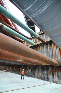
In addition, there are pipe relocations for both the factory‘s own supply and disposal systems and public utilities. Due to industrial pollution, large parts of the soil and groundwater in the area of the excavation pits are contaminated. The extracted groundwater and drainage water is cleaned and disposed of in a controlled manner in water treatment plants. The construction site is also inspected for unexploded ordnance in advance and during construction. Everything above and below the water in the Weser River and adjacent areas is searched for possible bombs from the Second World War.
The excavation pit is divided into four watertight sections (North 1 to North 4), which connect to the trench in the north and cross both a track field and the AMB service roads. The difference in height between the lowest (N4) and highest excavation pit base (N1) is approximately 12 m.
The individual excavation pit sections are separated from each other by watertight bulkheads. Excavation pits N4 (Fig. 4) and N2 will be constructed first so that the tunnel can be built, backfilled and covered as early as possible using the cut and cover construction method, thereby minimising disruption to AMB‘s works traffic. This will ensure that the connection to the immersed elements is completed on time.
The cut and cover section is followed by the trough construction method. The protective gallery sits on this trough, extending a further 565 m to the north and is designed to protect against flying sparks from the slag heap.
4.2 Excavation Pit South of the Weser
 5 | Southern construction site in Seehausen with the sheet pile wall to the Weser river in the foreground
Credit/Quelle: Eric Shambroom Photography
In contrast to the northern section, which is used for industrial purposes, the route in the south passes through the village of Seehausen, crossing the Hasenbürener Landstraße road. To maintain traffic flow, a diversion with a temporary bridge over the northernmost excavation pit on the south side will be set up (Fig. 5).
4.3 Construction Process
The construction processes in the north and south are similar. First, vertical shoring is installed using diaphragm walls, bored pile or sheet pile walls. After preliminary excavation, up to three anchor layers are installed, depending on the depth of the excavation pit. The subsequent dry excavation is carried out under the protection of groundwater lowering. This is followed by dredging in the flooded excavation pit. After cleaning the excavation base, threadbar micropiles are drilled from pontoons to secure buoyancy, and the pile heads are installed by divers. Subsequently, the underwater concrete is installed using the tremie method. Once the concrete has reached sufficient strength, the excavation pit is drained.
5 Construction of the Tunnel Elements in the Dry Dock
Since the two tunnel portals are not aligned, the tunnel takes an S-shaped curve in the Weser. Each of the six elements therefore has an individual curvature corresponding to the alignment in all three directions. The motorway enters the tunnel with a 4% gradient, winds its way underwater in the S-curve and rises back to the surface on the other side, also with a 4% gradient. This creates the shortest possible route for the final section of the A281 motorway.
 6 | Completion of the first two tunnel elements in the dry dock in Bremerhaven. The curvature of the route is clearly visible here
Credit/Quelle: Eric Shambroom Photography
Like the ramps and structures leading to the A281 junctions, the tunnel elements contain two lanes in each direction. The six elements are being constructed in a dry dock in Bremerhaven (Fig. 6). The tunnel‘s load-bearing structure is a closed, rigid, two-cell rectangular frame. The tunnel ceiling has a haunch on the inside at the corners of the frame. The tunnel floor extends beyond the outer edges of the tunnel walls, forming lateral toes. Taking into account the polygonal design of the tunnel blocks, the width of the emergency walkway was increased to 1.02 m. The clearance height is 4.70 m.
The width of the elements is just over 23.00 m across the toes and the height from the lower edge of the base to the upper edge of the ceiling is approx. 8.50 m. Only in the section of the emergency bays and the ventilation niches the total width is approx. 28.00 m and the total height approx. 10.00 m. The length of the elements varies between 115 and 125 m, consisting of 12 respectively 13 individual blocks of 9.50 m.
The dock was initially prepared so that the dock floor in particular could be used for the construction of the polygonal concrete elements. Special attention is paid to the subsequent floating of the elements, i.e. adhesion between the substructure and the concrete base must be ruled out. The base is constructed using permanent timber formwork, which is fastened with screws.
 7 | Formwork, reinforcement and concreting sequence for the segments
Credit/Quelle: Wayss & Freytag
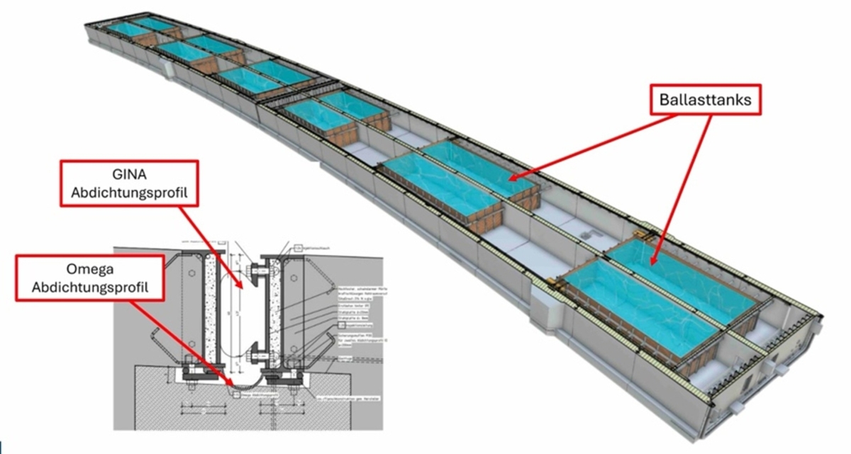 8 | Overview of the ballast tanks in a tunnel element and a detailed cross-section of the GINA and Omega sealing profiles
Credit/Quelle: Wayss & Freytag
The individual tunnel blocks are manufactured in a semi-monolithic configuration. After the base has been formed, reinforced and concreted, the central wall is erected so that the outer walls and ceiling can then be reinforced and concreted in one go (Fig. 7). In addition, the sand injection pipe for subsequent underflushing is laid on the outer toe. Once afloat, the freeboard of the individual elements is only 30 to 50 cm. In addition to the defined weights of reinforcement and built-in components, the weight of the concrete is also a decisive factor. Therefore, constant monitoring of the concrete density of each individual concrete pour is of utmost importance. The target and actual concrete density are continuously compared and, if necessary, corrected in consultation with the concrete manufacturer. All visible concrete surfaces are finished with smooth, level formwork as exposed concrete.The construction process was planned in-depth due to the tight time frame. The direction of work was determined from the centre outwards, so that four formworks could be used in parallel. Two 120 m long elements, each weighing a total of 22 000 t, are being constructed simultaneously, one behind the other.
In addition to the concrete construction work, special focus is placed on the temporary equipment for the towing and lowering processes. In addition to the ballast tanks (Fig. 8), a piping system for filling and draining the ballast tanks is installed, as well as the associated control system, lighting, ventilation and access points. Furthermore, the tendons must be laid and the prestressing applied. Before flooding the dock, the tunnel elements are sealed at both ends with pressure-water-tight concrete bulkheads equipped with doors and pipe penetrations.
6 Immersed Tunnel in the River Weser
6.1 Dredging the Trench
Before the tunnel elements are immersed, a trench with a slope of 1:5 is constructed between the north and south immersion channels in the Weser using the dredging method. At its deepest point, the excavation base is approximately 23 m below the average water level of the Weser. On both sides of the trench, transition areas connect to the respective cut and cover construction sites. In the bank area, the shoring consisting of combined sheet pile walls is mainly installed from floating installations. To secure the Weser bank in relation to the future slope line of the trench, sheet pile walls are constructed parallel to the river‘s fairway and secured with horizontal anchors.
6.2 Transport of the Concrete Elements
The concrete elements must be towed from the dry dock in Bremerhaven to the construction site in Bremen. The ballast tanks are flooded and their tightness is checked. The ballast tanks are then drained, the dry dock is flooded until it reaches the external water level, and the elements are floated in a controlled manner.
As soon as the elements are afloat, they are pulled out of the dry dock with winches, taken over by tugs and manoeuvred through the lock “Kaiserschleuse” in Bremerhaven to the Weser shipping channel. With the tide, they are pulled by two tugs at the primary end and pushed by another at the secondary end. A fourth tugboat accompanies the convoy so that a replacement is available if one of the tugs fails. The convoy heads for Bremen at a speed of approximately six knots. For passage through the locks, the tow is reduced to one tugboat and one brake tugboat. After passing through the narrow Oslebshausen lock, the elements are parked in three different harbour basins in the industrial harbour until they are lowered.
6.3 Preparations for the Lowering Process
As preparatory work, underwater explosive ordnance detection and dredging work to construct the trench will take place while shipping traffic continues, as this section of the Weser is a maritime shipping route. The shipping channel will be restricted at times to allow the underwater work to be carried out.
The explosive ordnance detection and any subsequent underwater clearance pose particular challenges for those involved. First, foreign objects will be cleared from the riverbed, then the area will be surveyed and, if necessary, cleared of explosive ordnance using floating equipment and with the assistance of divers.
Large floating machinery is then used to dredge the tunnel trench to a depth of up to 23 m below the average water level. The excavated soil is loaded onto barges and dumped at a specified location in the Outer Weser. Approximately 350 000 m3 of soil must be excavated to achieve the required depth. This work will take place shortly before the lowering process so that the sediment load in the Weser fills the dredged trench as little as possible. The slopes of the trench are planned with a gradient of 1:5 without additional scour protection against crossing ships.
The concrete elements parked in the industrial harbour are prepared in a two-week cycle by setting up the survey tower and the access shaft and installing the control system. They are then towed to the lowering site and will be submerged in a south-to-north work direction.
6.4 Lowering the Elements
In the south, two elements will be laid inland in the dredged trench, then three elements including the emergency bay will be lowered into the Weser, and one element will be lowered in the northern shore area. It is particularly challenging to lower the last element in the north, as it must be floated over the fifth element before it can be immersed.
The lowering process is controlled by a immersion pontoon, which is moved both longitudinally and transversely by means of winches to ensure precise control. Once the elements are in position, the ballast water tanks are slowly filled until the weight of the tunnel element is slightly greater than its buoyancy. The first sealing level is already in place on the previous element using the GINA profile, which was previously installed in the dock. At this point, the element is connected to the previous element at the primary end using a pin-grabber construction and is supported at the secondary end by pins and hydraulic presses on the previously placed auxiliary foundations. A compression system is then used to lightly press the GINA profile against the previous tunnel element in order to drain the coupling joint (the space between the two tunnel elements). The water pressure pushes the two tunnel elements firmly together, further compressing the GINA profile (see Fig. 8).
To ensure the required bedding, the elements are underfilled with a water-sand mixture. Once the filling process is complete, the position of the element is secured horizontally by filling at the sides. To backfill and cover the elements, sandy soil is transported from the Outer Weser to the construction site by barge, restoring the riverbed to its former state. Coarse stones are placed above the element ceiling as anchor protection before the final level is constructed (Fig. 9).
 9 | Cross-section of the deepest immersed element in the Weser river after completion
Credit/Quelle: Wayss & Freytag
A so-called omega seal is installed in the coupling joint between the previously lowered and the new tunnel element. Together with the GINA seal, two sealing levels are thus provided. This is followed by the demolition of the bulkhead walls and the concreting of the coupling joint. Once the tunnel element has been underfilled and bedded, the permanent ballast in the form of the road substructure is installed inside and gradually replaces the ballast water. Finally, the ballast tanks are removed.
After lowering the tunnel elements and constructing the final joint between the last element and the cut and cover tunnel on the north side, the water-side shoring is dismantled to restore the original shoreline.
7 Conclusion
The Weser crossing is a particularly unusual construction project, mainly because it is being built as an immersed tunnel. Other challenges include the excavation pits, which are up to 30 m deep, the immersion during ongoing shipping traffic and the tidal range of over 4 m with the corresponding current speeds in the Weser. For the client, DEGES, this method has two main advantages: firstly, it is the more economical option compared to a bored tunnel, and secondly, the elements can be prefabricated in parallel nearby in Bremerhaven, away from the actual construction site. This reduces the construction time considerably.