Fibre-Reinforced Concrete Segments – From Laboratory to Large-Scale Tests

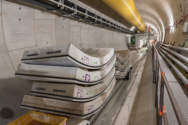
Due to the regulations currently applied in Austria, it is not possible to manufacture the segments required for TBM tunnelling from fibre-reinforced concrete. For this reason, numerous tests are being carried out as part of a research project supported by the Austrian Research Promotion Agency (FFG) in order to create a basis for the future use of fibre-reinforced concrete segments in Austria.

The project involves carrying out mixing tests with different fibre contents and materials, fresh and hardened concrete tests and large full-scale tests on segments. To ensure that the large-scale tests are as realistic as possible, they are carried out taking into account the normal force acting in a segment ring, which has a correspondingly positive effect on the load-bearing capacity of the fibre-reinforced concrete segments. Finally, the results obtained will be used to develop calculation approaches for dimensioning the fibre-reinforced concrete segments.

1 | Numerous tests are being carried out as part of a research project to create a basis for the future use of fibre-reinforced concrete segments in Austria
Credit/Quelle: ZaB

1 | Numerous tests are being carried out as part of a research project to create a basis for the future use of fibre-reinforced concrete segments in Austria
Credit/Quelle: ZaB

Introduction

In an age of scarce resources and the ever-increasing focus on the carbon footprint of the materials used in tunnelling, it makes sense to look at an alternative to the existing steel bar reinforcement. In numerous countries, segments with fibre reinforcement have already been successfully used in some projects in the past. Examples include the “Doha Metro Green Line”“ [1], “Deep Storm Water System – Main Tunnel” in Dubai [2] and the “Paris Metro” [1], which is currently under construction. Specifications for the design and construction of fibre-reinforced concrete components with and without additional steel bar reinforcement are available in some countries, such as Germany, but also internationally in the guidelines of the ITA (International Tunnelling & Underground Space Association). However, there is a contradiction between the “Fibre-reinforced concrete” [4] and “Concrete segment systems” [5] guidelines applicable in Austria due to the lack of verification of crack width limitation, which makes the use of fibre-reinforced concrete segments practically impossible. For this reason, a research project funded by the Austrian Research Promotion Agency (FFG) is being pursued to shed light on the entire process chain, from planning, production and quality management all the way to the realisation of large-scale tests. The result should provide a basis for the successful use of fibre-reinforced concrete segments in Austria.

Small-Scale Tests

Before the large-scale segment tests could be started, numerous concrete mixtures and laboratory-scale tests were carried out to better characterise the fresh and hardened concrete properties. Different fibre contents and materials were used in these mixtures in order to determine the influence of fibre type and content on the post-cracking tensile behaviour. In addition, the tests carried out in the laboratory are intended to verify the results of the large-scale tests and to establish a possible correlation between the two. The small-scale tests were carried out one day, 7 days and 28 days after concrete production to determine the development of the strength properties over time. The table in Figure 2 lists the concrete mixes produced in the laboratory and the tests carried out, including the age of the samples. The names of the sample mixtures are based on a consecutive numbering of the mixtures, an abbreviation of the fibre material used and the fibre dosage per m³. [6]

2 | Overview of the mixtures prepared in the laboratory and performed standard tests
Credit/Quelle: [6]

2 | Overview of the mixtures prepared in the laboratory and performed standard tests
Credit/Quelle: [6]
The production, storage and dimensions of the test specimens (cubes, cylinders, bending beams) were carried out in accordance with the provisions laid down in ÖNORM EN 12390 [7]. The bending tensile strength of the beams was determined by means of a three-point bending test according to ÖNORM EN 14651 [8] and different specimen ages. Two basic mixtures without the addition of structurally significant fibres were used as a reference for determining the characteristic strength values (see table, Fig. 3).

3 | Basic recipes for sample preparation in the laboratory
Credit/Quelle: [6]

3 | Basic recipes for sample preparation in the laboratory
Credit/Quelle: [6]
The GR 1 formulation was used for mixtures with a low fibre content (M0, M1_StF_30 and M2_StF_45). For the tests with a high fibre content (M3_StF_60, M4_StF_80, M1_KF_8, M2_KF_11 and M3_KF_15), GR 1 was adapted with regard to the proportion of paste and the grading curve (see GR 2), so that these are well embedded and distributed in the concrete matrix despite the increased fibre content. This adapted formulation is subsequently given the abbreviation GR2. A CEM I 52.5N was used as the cement in all mixtures. [6]

4 | Mean values of compressive strength on cubes after 24h, 7d and 28d
Credit/Quelle: ZaB

4 | Mean values of compressive strength on cubes after 24h, 7d and 28d
Credit/Quelle: ZaB
An additional 1.6 kg/m³ of polypropylene fire protection fibres were added to all mixtures to ensure that the laboratory mixtures could be processed as practically as possible. Figure 4 shows the mean values of the compressive strength on cubes after 1, 7 and 28 days as a bar chart. The colouring of the bars in grey and blue visualises the distinction between the initial mixtures in GR 1 and GR 2.

Figure 4 shows that the fibre dosage has no significant influence on the increase in the maximum achievable compressive strength. However, the use of fibre reinforcement makes the behaviour of the specimens much more ductile under compressive loading and increases the residual load-bearing capacity [9].

5 | Mean values of the bending tensile strengths fr1 und fr3
Credit/Quelle: [6]

5 | Mean values of the bending tensile strengths fr1 und fr3
Credit/Quelle: [6]
The flexural tensile strengths of the different compositions were analysed with regard to the residual flexural tensile strength at fr1 and fr3. The comparison of the results as mean values is shown in Figure 5. Using the three-point bending tests carried out on the notched bending beams in accordance with ÖNORM EN 14651 [8], a clear increase in strength with increasing fibre content was determined. Figure 5 also shows that the initial linear increase in bending tensile strength begins to level off as the fibre content continues to increase. [6]

Large-Scale Segment Tests

Based on the results of the previous small-scale tests, a standard practical dosage was selected for each fibre material in consultation with the project consortium. So far, six segments with a content of 45 kg/m³ and six segments with 11 kg/m³ macro synthetic fibres have been produced with the steel fibres. A previously used formwork was used for concreting the test segments. The type and dimensions correspond to those of a modern railway tunnel with an internal diameter of 8 m and a ring system of 6+0 segments with a large keystone. The segments used for the large-scale test have a width of approx. 1900 mm, a chord length of 4750 mm and a thickness of 350 mm. The opening angle is 60°. The segment formwork was set up in a precast concrete plant, which already had an ongoing fibre concrete segment production, and loaded with the concrete mixtures selected from the small-scale tests. The designation of the segments is based on the abbreviation of the mix used in the laboratory tests, the abbreviation “T” for segment and a consecutive numbering system. For all concrete mixtures, 1.6 kg/m³ of polypropylene fire protection fibres were added in order to achieve comparable fresh concrete properties. [6]

The large-scale tests were then carried out in Niklasdorf at the segment test rig of the University of Leoben. This test rig allows biaxial tests to be carried out on a real scale with segments that conform to construction site requirements. The modular design makes it possible to test different segment geometries and dimensions. [10]

6 | Full scale test rig with auxiliary and operating equipment
Credit/Quelle: [10]

6 | Full scale test rig with auxiliary and operating equipment
Credit/Quelle: [10]
The segment test rig (Fig. 6) consists of two main beams (1), which are mounted on two reinforced concrete supports using single-roller tilting bearings. Floating (2) and fixed (3) bearings are fixed to these with bolted connections. The modular design – movable bearings – allows tests to be carried out on segments with different chord lengths. The vertical forces are transmitted to the crosshead (6) via two 1 MN hydraulic cylinders (4) using tie rods (5). The horizontal force is applied via two 2 MN hydraulic cylinders (7). All hydraulic cylinders have a maximum stroke length of 200 mm and are controlled individually. The segment shoes (8) act as a link between the segment to be tested and the test stand. They are controlled via a PLC (programmable logic controller) with superimposed force control for each cylinder. The force is recorded via differential pressure measurement and load cells on the cylinders. The cylinder paths are
recorded via LVDTs (Linear Variable Differential Transformer) or laser sensors. [11]

7 | Position of sensors on the bottom side of the segmental lining element
Credit/Quelle: ZaB

7 | Position of sensors on the bottom side of the segmental lining element
Credit/Quelle: ZaB
An extensive setup of measurement technology is available to record deformations and detect cracks. Ten draw-wire sensors are attached to the intrados of the segment (Fig. 7), which record the vertical deflection of the segment during the test. Two additional draw-wire sensors record the change in chord length, which is associated with the deformation of the segment as the load increases. Two LVDTs (Linear Variable Differential Transformer) with a measuring length of 400 mm and eight strain gauges for crack detection are installed in the apex of the inner segment surface.

A Nikon Z7 full-format camera is attached to a linear drive on the end of the segment. To take the seven adjacent individual photos in the area of the apex, the load increase is stopped for a brief moment and the camera is moved step by step to the predefined positions by the linear drive. Using special software, the overlapping individual images are linked together in post-processing and the images of the different load levels are compared with each other. By setting and tracking digital markers, the crack opening and height can then be calculated with an accuracy of 0.07 mm per pixel. [12]

8 | Evaluation of the crack height and width based on the calculations done by using digital image correlation
Credit/Quelle: Kühbacher

8 | Evaluation of the crack height and width based on the calculations done by using digital image correlation
Credit/Quelle: Kühbacher
The calculation result of the digital image correlation shown in Figure 8 can be used to describe the crack progress during the test. For this purpose, the load points previously defined in the machine control system are approached, photos of the end face are automatically taken and compared with the original state. With the help of this data, it is possible to determine the existing deformations and the resulting forces in the compression and tension zone of the segment cross-section and thus subsequently draw conclusions about the fibre support effect. The functional principle and the calculations of the crack width in the large-scale segment test carried out at the Chair of Subsurface Engineering are described in detail in [13].

9 | Mounting of a segmental lining element to the test rig
  Credit/Quelle: ZaB

9 | Mounting of a segmental lining element to the test rig
  Credit/Quelle: ZaB
An indoor crane with a lifting capacity of 12.5 tonnes is available in the test hall in Niklasdorf for placing the test specimens, which weigh several tonnes. Figure 9 shows the placement of a segment in the test rig using the crane. This figure also shows the size of the segments used in the research project.

Test Sequence

10 | Overview of the load combinations performed up to now on the segmental lining elements
Credit/Quelle: [6]

10 | Overview of the load combinations performed up to now on the segmental lining elements
Credit/Quelle: [6]
To allow evaluation of the test results and subsequent comparison between the different segments, the absorbed forces and the resulting introduced bending moment in the symmetry plane of the segment and the associated deformations are used. For this purpose, the bending moment in its plane of symmetry is determined using the applied vertical and horizontal loads (FVZ, FHZ) and the segment geometry. The vertical deformation is recorded using the aforementioned cable sensors, which are positioned on the underside of the segment. Two load combinations with different horizontal forces were defined as the test sequence in order to take into account the influence of the normal force prevailing in the closed segment ring. The load scenario was thus carried out in a combined force application, which is modelled on a possible load on a segment in the installed state with defective annular gap filling. A horizontal force of 500 kN is applied to each of three segments and kept constant. Meanwhile, the vertical force is continuously increased until failure. In contrast, the remaining segments were subjected to a constant horizontal load of 1000 kN and the vertical force was increased until failure. An overview of the load combinations can be found in Figure 10. [6]

Results

11 | Overview of the load-deflection curves of all performed load combinations on the segmental lining elements
Credit/Quelle: [6]

11 | Overview of the load-deflection curves of all performed load combinations on the segmental lining elements
Credit/Quelle: [6]
If the results (Fig. 11) of the large-scale tests are compared with each other, the influence of the normal force is immediately apparent. Due to the greater normal force applied in load combination 2, higher loads can be absorbed by the component, as this has a positive effect on the vertically applied bending stresses. Furthermore, the results show that the steel fibres have a higher load-bearing capacity than the synthetic fibres. On the other hand, the different material behaviour of the two fibre materials shows that the synthetic fibres can absorb high loads almost constantly over a larger deformation range due to their material characteristics before the load-bearing capacity of the component begins to decline.

In general, Figure 11 shows that the results exhibit very little scatter – especially those of the synthetic fibre segments, which can be explained by the fact that these also have a much larger number of fibres crossing cracks due to the high fibre dosage.

Outlook

The fibre concrete mixtures from the small-scale tests of the research project provided insights into the fresh concrete properties and mechanical characteristics of the different test specimens. It was also possible to analyse the strength development in dependence on the sample age. Based on the findings from the small-scale tests, fibre dosages were selected for the production of the test segments. The results of the large-scale tests were also positive with low scatter. Furthermore, large-scale tests without the influence of a horizontal force with steel and synthetic fibres are planned. Numerical simulations on the behaviour of the splitting tensile forces due to the jacking cylinders are being carried out at TU Graz. Finally, quality assurance measures and a design concept will be developed.

Acknowledgements

The results presented in this report were obtained as part of the research project “Fibre-reinforced concrete segments”, which is supported by the Austrian Research and Promotion Agency (FFG) under grant agreement no. 886265. We would also like to thank the project partners ASFINAG, ÖBB, Porr, Kirchdorfer Fertigteil Holding, Master Builders Solution, Bekaert Underground Solution, Contec Fiber, Lafarge Zementwerke, D2-consult, Statik & Planung-Baumeister Büro DI Ulrich Horny, PCC Betonfertigteilberatung ZT, Material Consult Dr. Pichler ZT, ÖBV and TU-Graz for their financial and technical support.

Literatur/References
[1] U. Horny, L. Bayer, K. Schiesser, and O. Kliem, “Metro Doha Green Line: Fibre reinforced tunnel linings – Design and construction experience,” Geomechanics and Tunnelling, vol. 14, no. 4, pp. 347–355, 2021, doi: 10.1002/geot.202100016.
[2] V. Zeuli et al., “Structural design of precast segmental lining reinforced by steel fibres,” Geomechanics and Tunnelling, vol. 14, no. 4, pp. 356–366, 2021, doi: 10.1002/geot.202100020.
[3] J.-L. Bischoff and M. Eberli, “Grand Paris Express Lot 16 – Sustainable infrastructure development in Paris,” Geomechanics and Tunnelling, vol. 15, no. 6, pp. 767–773, 2022, doi: 10.1002/geot.202200060.
[4] Richtlinie „Faserbeton“, Österreichische Vereinigung für Beton- und Bautechnik, 2008.
[5] Richtlinie „Tübbingsysteme aus Beton“, Österreichische Vereinigung für Beton- und Bautechnik, 2009.
[6] M. Kühbacher, “Full scale tests on steel and synthetic fiber reinforced tunnel lining segments,” Vortrag bei Underground Construction Conference Prag 2023.
[7] ÖNORM EN 12390 „Prüfung von Festbeton“, Austrian Standards, 2019.
[8] ÖNORM EN 14651 „Prüfverfahren für Beton mit metallischen Fasern – Bestimmung der Biegezugfestigkeit“, Austrian Standards, 2007.
[9] G. König and C.-A. Graubner, Trends in tall building: International conference/Tendenzen im Hochhausbau: internationale Konferenz, September 5–7, 2001, Frankfurt am Main. Leipzig, Darmstadt: IMB, Universität Leipzig; Technische Universität Darmstadt, 2001.
[10] P. Gehwolf et al., „Konzeptionierung, Realisierung und erste Ergebnisse eines neu entwickelten Tübbingprüfstands“, Berg Huettenmaenn Monatshefte (BHM Berg- und Hüttenmännische Monatshefte), vol. 160, no. 12, pp. 530–534, 2015, doi: 10.1007/s00501-015-0428-4.
[11] M. Kühbacher, „Herstellung und Durchführung von Großversuchen an Faserspritzbetontübbinge“, Berg Huettenmaenn Monatshefte (BHM Berg- und Hüttenmännische Monatshefte), vol. 167, no. 12, pp. 556–561, 2022, doi: 10.1007/s00501-022-01301-8.
[12] P. Gehwolf, R. Wenighofer, R. Galler, “Current status of tubbing research – Insight into the research activities at the Chair of Subsurface Engineering,” Geomechanics and Tunnelling, vol. 10, no. 6, pp. 753–759, 2017, doi: 10.1002/geot.201700043.
[13] L. Limbacher, „Fotogrammetrische Auswertung von Rissentwicklungen am Tübbing während Belastungsversuchen“, Bachelorarbeit, Subsurface Engineering, Montanuniversität Leoben, Leoben, 2023, unveröffentlicht.
x

Related articles:

Issue 02/2022 Grand Paris Express

Steel-Fibre-Reinforced Tunnel Segments Improve Carbon Footprint

Comprehensive climate-relevant optimisations are possible above all in the production of cement, concrete and steel. For example, the production of cement in Germany alone generates about 0.6 t of CO2...

more
Issue 01/2011

Steel-fibre-reinforced segmental linings: State-of-the-art and completed projects

Introduction Upon the appearance of steel-fibre-reinforced concrete on the European market in the 1970s, neither standards nor guidelines for the design and dimensioning of this new material were...

more
Issue 03/2018

Steel Fibre Reinforced Concrete for Tunnel Lining Segments

Compared to conventional steel reinforcement, the usage of steel fibre reinforced concrete segments for tunnel linings offers many advantages. The production process of the segments is simpler and the...

more
Issue 04/2012

Segmental Ring Design – New Challenges with High Tunnel Diameters

1 Introduction Tunnel lining with segmental rings behind TBMs are reinforced concrete elements and must be calculated and designed according to the standards of reinforced concrete constructions....

more
Issue 07/2015 Brugg Contec

EMPA long-term Load Test for Synthetic Reinforcement Fibers

The durability of synthetic fibers in aggressive environments is often questioned. A long-term test undertaken by the Swiss material tes­ting and research institute (EMPA) as part of a KTI project...

more