Ibbenbüren Mine Water Drainage Tunnel Nearing Completion
 Credit/Quelle: Wayss & Freytag
 Credit/Quelle: Wayss & Freytag
 Credit/Quelle: Herrenknecht AG
 Credit/Quelle: Herrenknecht AG
 Credit/Quelle: RAG
 Credit/Quelle: Herrenknecht AG
 Credit/Quelle: RAG
 Credit/Quelle: Wayss & Freytag
 Credit/Quelle: Herrenknecht AG
 Credit/Quelle: Wayss & Freytag
 Credit/Quelle: Wayss & Freytag
 Credit/Quelle: Wayss & Freytag
 Credit/Quelle: Wayss & Freytag
 Credit/Quelle: Wayss & Freytag
 Credit/Quelle: Wayss & Freytag
Construction of the Ibbenbüren mine water drainage tunnel has been underway since October 2021; the tunnel is designed to collect the mine water from the former hard coal mine for treatment. The joint venture comprising Wayss & Freytag Ingenieurbau AG and Ed. Züblin AG has, amongst other things, driven the 7.2 km-long tunnel using two TBMs, and constructed the channels and a discharge structure. Following a comprehensive project presentation in tunnel 5/2023, this article reports on the progress of the works and the lessons learnt.
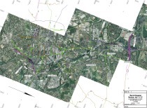
As part of RAG Aktiengesellschaft’s long-term mine water management programme, a 7.2 km long drainage tunnel (Fig. 1) with segmental lining was constructed in Ibbenbüren, and 260 m of pipework was laid to the discharge structure using open-cut construction methods in order to continuously drain mine water from two former mining
areas. For the first time, mechanised tunnelling was carried out using two Variable Density Tunnel Boring Machines (VD TBMs) with an internal diameter of just 3.6 m (Fig. 2). The challenges involved the complex, variable geology, high water pressures and restricted access in the TBM area. In addition, the annular gap was backfilled with pea gravel in some sections to ensure drainage capacity.
1 Project Description and Key Features
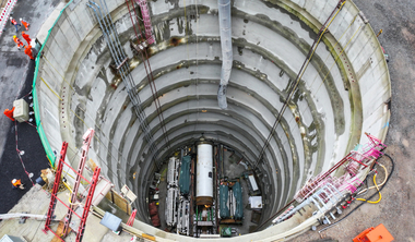
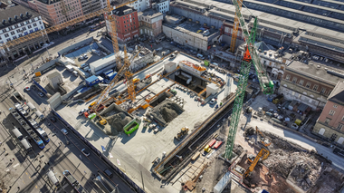
The mine water generated in the western and eastern sections of the disused hard coal mine is collected via the new drainage tunnel and channelled to the new mine water treatment plant (which is not, however, part of the project) at the western end of the tunnel. Furthermore, the tunnel lining is designed to allow drainage with planned penetration points combined with a water-permeable backfill of pea gravel. The mine water drainage tunnel has a slight gradient running from west to east, from the outlet structure and launch shaft (Fig. 3) via the central shaft (Fig. 4) to Shaft 1 (Oeynhausen shaft), allowing the collected water to flow freely to the water treatment plant (Fig. 5). As the mine water from the western and eastern fields has different levels of mineralisation and is therefore treated separately, it is routed through two separate channels within the mine water drainage tunnel.
The mine water drainage tunnel has a total length of around 7400 m. To the west, it is connected to the existing network, via the so-called outlet structure. Over a length of 260 m, it is linked to the transfer structure erected in the launch shaft via DN3600 pipes laid using the open-cut method. In the launch shaft (see also Fig. 3), the first Variable Density TBM began the 3244 m long west drive to the central shaft. The second VD TBM commenced the 3894 m long eastern drive there at a later date (Fig. 6). With an external diameter of 4.5 m and a single-shell, 45 cm thick segmental lining, the tunnel has an internal diameter of 3.6 m. In both tunnelling drives, five concrete segments plus a keystone were installed (Fig. 7). In some sections of the drives, a 15 cm thick drainage layer of pea gravel was applied, whilst in the remaining sections the annular gap was filled with two-component mortar. This results in a final excavation diameter of 4.8 m.
2 Tunnel Excavation
Tunnel excavation on the western section began in January 2023 at the outlet structure and reached the central shaft in June 2024. The overburden at the start of excavation was approximately 7 m above the tunnel crown and around 65 m at the target shaft. In parallel, work was carried out in the central shaft to prepare for the start of the eastern tunnel drive in September 2023. In February 2025, the eastern TBM (Fig. 8) reached its destination in Shaft 1. For the western tunnel drive, the entire TBM was dismantled and retrieved from the central shaft. Once the eastern drive had been completed, all components of the TBM were pulled back into the central shaft and dismantled. Only the shield skin remained in the ground at Shaft 1.
The challenging and variable ground conditions posed a major challenge. The strata encountered included shell limestone, Zechstein and the Ibbenbüren strata – comprising claystone, siltstone, sandstone and conglomerates – with sections containing coal deposits. In particular, the hydrogeological conditions varied considerably, with high rock and fissure water pressures of up to 4 bar. This was compounded by heavy, localised water inflows. In total, two geological fault zones had to be passed through. The ingress of mine gas, which had to be taken into account during the planning stage, did not occur.
From both a geotechnical and hydrogeological perspective, the two tunnelling drives were subject to very similar conditions. Only the first 500 m of the western drive passed through loose soil. Thereafter, tunnelling was carried out mainly in hard rock.
2.1 Experiences Gained During Tunnelling
The two Variable Density TBMs proved their worth on the project. However, the three planned driving modes (see also tunnel 5/2023) could not be implemented, as water was encountered over long stretches rather than the expected localised and temporary water inflows. In consultation with the client, pea gravel also had to be blown into these areas to ensure the required drainage performance of the tunnel. The pea gravel was introduced at the top of the segment ring and at three further positions in the upper section. In addition, a check valve was installed to prevent backflow and washout of the pea gravel.
This was compounded by challenging and variable geology. Abrasiveness was very high and the tools suffered significant wear, leading to frequent tool changes in both tunnel headings. The claystone encountered tended to cause sticking. Its variability affected further work processes and placed a corresponding strain on the centrifuges used.
Mine gas, which had to be taken into account during the planning stage, did not occur during the construction phase. For this eventuality, the entire system had been encapsulated, meaning that any gases present would have been detected at the separation plant.
Passage through former adits and mined-out seams proceeded without any problems. Only a few cavities were encountered, so backfilling with mortar remained within reasonable limits. Groundwater was expected to occur only locally and temporarily; consequently, the water pressure should have eased over time.
Another distinctive feature is the size of the VD TBM (Fig. 9). With an internal diameter of 3.6 m and extensive technical components, the space available for necessary work was very limited. The installation of equipment, maintenance work or troubleshooting could only be carried out by partially dismantling other components. The cramped conditions posed an additional challenge for the personnel. Here, a well-developed technology reached the limits of the space required.
One component of the VD TBM, the slurryfier box – which liquefies the material fed in via the screw conveyor by adding the suspension – proved not to be entirely effective under the prevailing conditions, particularly during the eastern tunnelling section. Due to high pressures – resulting from the 70 m deep launch shaft – Herrenknecht AG had to develop a project-specific seal between the screw outlet and the slurryifier box.
Controlling the conveying circuit was also challenging due to the small size of the machine. The combination of considerable shaft depth and a small machine diameter led to very short reaction times in response to fluctuations in support pressure within the excavation chamber, caused by the very low compensation volume in the pressure chamber. The TBM had to be controlled with great precision and reacted extremely quickly to pressure changes.
Maintaining the circulation system via the 70 m deep central shaft during the eastern tunnel drive required considerable effort. Due to the high pressures, wear and tear on the pumps, machinery and pipework occurred significantly more frequently than normal. The situation would have become difficult in the event of pressure spikes or a failure of the conveying circuit. This problem was solved by using an emergency overflow fitted with a stone trap. In addition, rupture discs were installed to reduce the flow rate. However, these additional components required extensive maintenance.
3 Construction of the Central Shaft
The construction of the 70 m deep central shaft, with a diameter of 30 m, proved difficult as the ground encountered throughout the area was non-homogeneous. For this reason, instead of using blasting – as originally planned – the ground was removed using excavators. Following the installation of the concrete floor, preparations for the launch of the East TBM and the entry of the West TBM, the shaft structure was constructed after the completion of the tunnelling work and the installation of the channel in both tunnels (Fig. 10). By mid-June 2026, the segment linings of the two tunnels had been connected to the DN3600 sewer pipes and to two 1.50 m wide connection structures in each tunnel, constructed using in-situ concrete. The final 30 m of the channel were also installed. Lastly, a lift system and various fit-outs will be installed, and the excavation pit will be backfilled with approximately 52 000 m³ of soil by the end of October 2026. An operations building will then be constructed.
4 Discrete Connections
In addition to the drainage openings (Figs. 11 + 12), discrete boreholes were drilled at a total of five locations along the tunnel. A small drilling rig with an anchor drilling machine was used for this purpose. Despite the confined space, the drilling starting point had to be positioned at right angles to the tunnel centreline. A short drill rig with short drill rods was used to carry out the boreholes, which were up to 15 m deep in the West Tunnel and up to 30 m deep in the East Tunnel. At tunnel metre 1032, drilling commenced on the Dickenberger West Adit (see also Fig. 5), through which mine water had previously been collected and drained. Also in the western section, two boreholes were drilled downwards at three separate locations into the disused smaller adits. A total of nine discrete boreholes were drilled in the western section, while two discrete boreholes were drilled in the eastern section.
Once the discrete connections had been drilled in the West Tunnel and tunnelling in the eastern section had progressed, work began on installing the channel from the central shaft, working backwards to the outlet structure.
5 Construction of the Channels
With the completion of the western tunnel drive, work began on constructing the channels in the western section. Following the completion of the eastern tunnel drive, construction of the channels in this section commenced
(Table 1). The eastern channel was completed in early 2026. As of May 2026, the only remaining task was to close the gap between the two sections in the central shaft.
Two fundamentally different types of channel were installed in the western and eastern sections (see also Fig. 7).
In addition, there were a total of ten different variations, for example to accommodate left- and right-hand bends, or short and long elements to align with the segment joints. There were also special elements with recesses for the supply pipes from the drainage systems.
Installation was carried out using a specially designed, self-propelled channel train (Figs. 13 + 14), which consisted of three main components (station, portal carriage with two crane systems, and a concreting unit). Several trains were used to deliver concrete and precast channel
sections. The concrete train was positioned on the station platform equipped with a walking mechanism. From here, the concrete was pumped to the concreting unit. A concrete spreader was used to place the concrete into the berms on the left and right, as well as into the central channel in the eastern section. The precast elements were set to the correct height using shims of various thicknesses and then grouted underneath with a specially developed cement-free mortar. This installation process took place within the 40 m long portal carriage (Fig. 15).
During standard installation (east), an average of approximately 26.70 m of precast channel sections and around 26.70 m of concrete for the berms were produced. The peak output over a 24-hour period amounted to 55 m of precast sections installed and 70 m of concrete placed.
6 Outlet Structure and Open-Cut Construction
Following the completion of the western tunnel drive and the installation of the channels from the central shaft to the launch shaft, the 260 m long section constructed using the open-cut method was also equipped with precast channel components.
At the outlet structure, the mine water is diverted from the channel into two DN800 pipes, which later run through an open channel to the water treatment plant. The launch shaft was cleared, the logistics level was extended, and the sewer pipes were connected to the segmental tunnel within a cast-in-situ concrete structure, the transition shaft. All remaining work here will be completed by the end of 2026.
7 Conversion of Shaft 1
Following the completion of the eastern tunnel drive and the discrete drilling, work began on the connecting cavern, situated at a depth of around 100 m, linking the tunnel to the base of Shaft 1.
The base area, secured with cast-iron segments, was lined to a height of 8 m with in-situ concrete. The 100 m deep shaft has an existing diameter of 4.40 m, which will be reduced to 3.60 m following the final lining.
Once the old headframe has been braced, the remaining 90 m will be constructed vertically using the segmental lining method from September 2026. The segmental lining consists of 25 cm-thick elements backfilled with mortar. In the shaft head area, the lining will again be constructed using in-situ concrete up to ground level.
8 Commissioning
As numerous works will continue across the various project sections until early 2027, full commissioning is scheduled for summer 2027. Mine water is already flowing through the West Tunnel. The cost-intensive mine water management using pumps is thus a thing of the past. In future, the modern mine water drainage tunnel will collect the mine water from the decommissioned Ibbenbüren coal mine and, after treatment, return it to the natural cycle.