Three-Component Approach: Double-Layer Pressurized Waterproofing System With Planned Block Backing

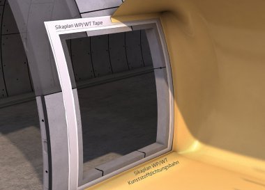
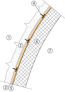
The “three-component approach” for high waterproofing requirements is a new waterproofing system especially for high water pressures. It is presented here as a possibility that can be implemented in construction practice. A geosynthetic clay liner (GTD – or bentonite mat) is installed as the first layer behind the 3 mm thick tunnel sealing membrane that retains water under pressure, instead of the usual protective and drainage geotextile. Laboratory tests as well as practical application on the tunnel construction site show that the use of bentonite mats and plastic sheet membrans (PSM) as a double-layer pressurized waterproofing with simultaneous extended ridge gap injection (block backfill) is a promising alternative to the double-layer system with PSM and could represent a new state of the art.

1 Introduction

New tunnel constructions increasingly pass through ecologically sensitive areas, and the requirements for groundwater protection are increasing. Often, the permanent reduction of mountain water is not approved for ecological reasons. In these cases, tunnel structures must be formed against pressurised water, i.e. for high water pressures. However, the higher the water pressures rise, the more demanding are the requirements for tunnel sealing systems. 

1 | Application of the sealing system with three components: geosynthetic clay sealing barrier (bentonite mat), geomembrane,
block backing and concrete inner shell
Credit/Quelle: Marc Meissner

1 | Application of the sealing system with three components: geosynthetic clay sealing barrier (bentonite mat), geomembrane,
block backing and concrete inner shell
Credit/Quelle: Marc Meissner
At the same time, increasingly complex tunnel sealing measures have to be implemented on the construction site. For water pressures above 30 m, for example, special building-specific measures must be specified [2], such as double-layer sealing systems with testable chambers or sealing membranes with a thickness of 4 mm. Both options have proven difficult to implement in construction practice. 

2 | In the case of high-water pressures, the new multi-component system is a safe measure that can be implemented in practical construction applications
Credit/Quelle: Marc Meissner

2 | In the case of high-water pressures, the new multi-component system is a safe measure that can be implemented in practical construction applications
Credit/Quelle: Marc Meissner
In this article, a new waterproofing system for high demands, especially high water pressures, is presented as a possibility that can be implemented in construction practice: A geosynthetic clay liner (GTD – or bentonite mat as well) is installed as the first layer behind the 3 mm thick, tunnel sealing geomembrane that retains pressurised water, instead of the usual protective and drainage non-woven fabric (Figs. 1 and 2).

In order to ensure the functionality of this system, a planned filling of cement on the inner shell is part of the proposed solution.

In the case of high-water pressures, a full-surface bedding of the plastic liner is required against the in-situ concrete inner shell and

the bentonite mat must be clamped between the sprayed concrete (sealing support) and the geomembrane in order to fulfil the sealing function to the full extent.

2 Sealing Systems for Tunnel Construction

As a general rule, a distinction must be made between pressure-tight and pressure-relieved sealing systems. The latter have been used successfully for many years and are therefore not discussed further in this article.

In practice, in the case of pressurised water-retaining systems, leaks and damage occur time and again, and this can only be remedied at great expense. Often the renovation is not permanent either. The constructor gets a “repaired structure”. The main focus in the following explanations is therefore the prevention of damage and not restoration.

The most common method for sealing against high water pressures with geomembranes in the field of mining tunnelling is to produce a leak-free welded geomembrane with an inner shell of in-situ concrete. Leakages have occurred in many construction projects, and these can have a whole range of causes. The causes must be differentiated between those that are found to be
related to faulty construction and those that are systemrelated.

The following leaks can be attributed to construction work [5]:

Damage to the geomembrane in the course of reinforcement installation

Damage during formwork carriage positioning

Damage during concrete filling

Improper installation of the geomembrane system, leaky welds, strains at cross-section transitions, etc.

In the case of high-water pressures, system-related damage to the geomembrane can also occur [5]:

Large water pressures require rigid, large internal formwork thicknesses. The concrete is usually compacted with formwork vibrators. Often, the outside of the inner shell has cavities or defects. On the one hand, these are caused by insufficient compaction with formwork vibrators as well as a result of large internal formwork thicknesses and a high reinforcement content, which makes professional and/or full-scale concreting and compaction difficult. On the other hand, these defects are caused by air bubbles that cannot escape at the plastic liner and therefore sometimes create cavities which are several centimetres in size.

In the final state, the water pressure acts from the outside. In which case, damage to the plastic liner cannot be ruled out and/or, is even likely.

In many projects, grouting the gap between the geomembrane and the in-situ concrete inner shell with cement (so-called extended ridge gap grouting/planned block backfilling) has proven to be a suitable means of avoiding this “system-related” damage. In addition, this grouting, which takes place when the mountain water level is still reduced, can also “repair” small construction-related damages. Small defects in the plastic liner are closed with the cement suspension and sealed to such an extent that the leaks are practically non-existent.

In principle, long-term resistant geomembrane made of plasticiser-free polyolefins or plasticised polyvinyl chloride (PVC-P) are used for the safe sealing of a tunnel. To avoid migration or leaching of the plasticiser, careful testing of the sealing material should be carried out with regard to long-term resistance and in terms of the harmlessness of the material with regard to the environment.

2.1 Building Up Layers With the Geomembrane

3 | Sealing system with geomembrane
Credit/Quelle: Marc Meissner

3 | Sealing system with geomembrane
Credit/Quelle: Marc Meissner
The layers of the waterproofing system (from the outside to the inside) are basically built up as follows in accordance with ZTV-ING (Fig. 3).

2.1.1 Sealing Support

Coarse unevenness in the sprayed concrete shell is evened out with a layer of sprayed concrete approx.
4 to 5 cm thick (made of fine-grained, ideally round grain, sprayed concrete). Steel parts such as anchor heads are injected and holes are sealed. Likewise, hosing from the tunnelling is injected with this layer.

This creates a sufficiently even sprayed concrete surface to ensure that the sealing system is not damaged during the concreting process. 

2.1.2 Protective Geotextile on the Outside

Because the geomembrane is pressed against the sealing support made of sprayed concrete (1st layer) during the concreting of the inner shell, protection is necessary at this point. A mechanically bonded non-woven fabric with a surface weight of at least 900 g/m² is used as the protective geotextile on the outside (2nd layer). 

2.1.3 Fastening System

In addition to fixing the protective geotextile on the outside, the fastening system serves to temporarily fix the sealing system to the sprayed concrete outer shell and must not damage the geomembrane. During the concreting of the cast-in-situ concrete inner shell, the plastic liner may be stressed. Therefore, multi-point fastening systems must always be equipped with a predetermined breaking point in order to avoid damage to the geomembrane.

2.1.4 Geomembrane (PSM)

The main sealing element, the geomembrane, is installed on the protective non-woven fabric. Geomembranes (at least 2 mm thick) are used in drained tunnels. They should be at least 3 mm thick in undrained tunnels. They are equipped with a bright signal layer on the air side in order to find damage quickly and to improve the lighting conditions in the tunnel during the installation work.

2.1.5 Waterstops

Waterstops are made of the same type of geosynthetics as the geomembrane and are mainly used on the outside, lying in the joint area of two tunnel blocks to divide the geomembrane sealing level into delimited fields. They are welded directly onto the pre-installed geomembrane so that in the event of a leak, the leakage can be localised and repaired in a targeted manner.

Waterstops are usually 60 cm wide and have a total of six waterstop bars. Ideally, factory-fitted fastening options for injection hoses are provided between the waterstop bars. On both sides of the block joint, two radially circumferential injection hoses are positioned between the waterstop bars in order to activate the waterstops by subsequent injection, if necessary.

2.1.6 Protection Membrane

In pressurised water-tight tunnels with an all-round geomembrane, additional protection against damage is required in the invert area. This can be a second protection geomembrane (at least 3 mm thick) or mat-reinforced protective concrete. The construction sequence should generally be selected in such a way that the geomembrane in the bottom no longer has to be driven over. The protection geomembrane should be laid over the base/vault connection reinforcement.

2.1.7 Integrated Testing and Injection
System as a Back-Up System

4 | Injection and vent lines in the external joint tape
Credit/Quelle: Marc Meissner

4 | Injection and vent lines in the external joint tape
Credit/Quelle: Marc Meissner
In the case of pressure-tight tunnels with a pressure level of at least 1 bar (measured from the tunnel floor), an integrated testing and injection system is provided in accordance with ZTV-ING Part 7 Section 5 [3], which can be used to detect leaks (Fig. 4). In the event of water escaping from the inspection/injection openings, the damaged area can be sealed by injecting synthetic resin or acrylate gel.

A supplement to or variant of the system prescribed in ZTV-ING [3] involves the backing (extended ridge gap grouting/planned block backing) of the entire inner lining block with cement (suspension). The basic idea here is to ensure a fully concreted inner shell before the mountain water drainage is injected and the water pressure on the outside presses the geomembrane on the outside of the inner shell. This system prevents possible damage that can result from the water pressure pushing the geomembrane onto uneven surfaces or, in the worst case, onto the exposed reinforcement on the outside of the inner lining of the tunnel. 

2.2 Sealing Against Seepage or Pressurised Water

When sealing in tunnel construction, a distinction is made between seepage water and pressurised water sealing (single to multiple layers).  

2.2.1 Umbrella Sealing System

5 | Seepage water seal against non-pressing water
Credit/Quelle: Marc Meissner

5 | Seepage water seal against non-pressing water
Credit/Quelle: Marc Meissner
In a tunnel with pressureless water accumulation, the structure is protected against moisture with an umbrella seal and the seepage water is routed via the longitudinal drainage to the foot of the tunnel with the following layer structure (Fig. 5) (from outside to inside):

Sprayed concrete outer shell with sealing support

Protective geotextile

2 mm thick geomembrane (single layer)

Concrete inner shell. 

2.2.2 Single-Layer Pressurised Water Seal

6 | Single-layer pressurised water seal (pressurised water retaining)
Credit/Quelle: Marc Meissner

6 | Single-layer pressurised water seal (pressurised water retaining)
Credit/Quelle: Marc Meissner
In the case of pressurised water, a pressurised water-retaining single-layer PSM is installed all around with bulkhead waterstops in the block joints and the layer structure (Fig. 6) is as follows (from outside to inside):

Sprayed concrete outer shell with sealing support

Protective geotextile

3 mm thick geomembrane (single layer) or

Waterproof reinforced concrete inner shell
(in accordance with ZTV-ING [3]).

2.2.3 Two-Layer Pressurised Water Seal

If the water pressure is very high (> 3.0 bar), special measures must be taken to create a leak-free tunnel structure. So far, the ZTV-ING [3] has referred to the need to take special measures that have to be defined in individual cases. This can be, for example, either a particularly thick geomembrane (> 4 mm) as a single-layer pressurised water seal or a two-layer geomembrane system with vacuum testing. In the past, both design variants did not lead to the desired project success and therefore in practice, have no longer been used in recent years.

Here, too, bulkhead waterstops are installed in the block joints and the layer structure is as follows (from outside to inside):

Sprayed concrete outer shell with sealing support

Protective geotextile

3 + 2 mm thick plastic liner (two layer with vacuum test system)

Waterproof reinforced concrete inner shell

3 Double-Layer Pressurised Water Seal With Three Components

7 | Bentonite mat installed in the vault
Credit/Quelle: Marc Meissner

7 | Bentonite mat installed in the vault
Credit/Quelle: Marc Meissner
The system presented here describes an approach for sealing systems with water pressures above 3 bar. The multi-component seal (MCS) (Fig. 7) consists of the following design elements:

The geosynthetic clay barrier (GCS) – i.e., the
bentonite mat 

A layer of geomembrane (3 mm thick)

The surrounding block backing as extended ridge gap grouting with cement suspension

The waterproof concrete inner shell including internal waterstops and corresponding external waterstops in accordance with ZTV-ING [3]

3.1 Description of the System

The geosynthetic clay barrier consists of three layers, namely a highly swellable layer of sodium bentonite powder, which is encapsulated by needling between a mechanically bonded cover non-woven fabric and a ribbon fabric. In the event of moisture, the bentonite powder in the geosynthetic clay barrier swells and thus achieves the sealing function.

In addition, the geosynthetic clay barrier is provided with an even, polyethylene coating for use in tunnel construction. Among other things, this coating prevents the swollen bentonite from drying out. Another desirable
side effect of the coating is safe installation without major dust exposure.

In the tunnel, the geosynthetic clay barrier is first applied to the sprayed concrete outer shell (sealing base) and fastened with an overlap. Welding is not necessary. The second sealing level, the geomembrane, is applied to this first sealing level, and then the concrete inner shell is installed.

Above all, the advantages of the new multi-component seal compared to the classic geomembrane, double layer seal include much simpler practical feasibility in terms of construction. The geotextile protective layer is omitted (this protective function is taken over by the geosynthetic clay barrier), the 2nd layer, the geomembrane, and thus the complex leak tests using a vacuum test system.

To ensure the sealing function of the geosynthetic clay barrier, a friction-locked installation between the sealing support and the plastic liner is necessary, which can only be achieved by means of a planned block backing. The surrounding block backing with cement suspension is part of this new type of sealing system and must therefore be provided.

3.2 Use of Bentonite Mats in Tunnel
Construction

8 | Double-layer pressurised water seal as a multi-component system with bentonite mats
Credit/Quelle: Marc Meissner

8 | Double-layer pressurised water seal as a multi-component system with bentonite mats
Credit/Quelle: Marc Meissner
9 | The bentonite mats are installed overlapping using a suitable application device
Credit/Quelle: Marc Meissner
9 | The bentonite mats are installed overlapping using a suitable application device
Credit/Quelle: Marc Meissner
10 | Installation with a machine-guided laying traverse due to the high specific weight of the bentonite mats
Credit/Quelle: Marc Meissner
10 | Installation with a machine-guided laying traverse due to the high specific weight of the bentonite mats
Credit/Quelle: Marc Meissner
11 | Multi-point fastening of the bentonite mats according to the grid in the vault, wall and base
Credit/Quelle: Marc Meissner
11 | Multi-point fastening of the bentonite mats according to the grid in the vault, wall and base
Credit/Quelle: Marc Meissner
12 | The subsequent geomembrane is temporarily fastened to the attachment points of the geosynthetic clay barrier
Credit/Quelle: Marc Meissner
12 | The subsequent geomembrane is temporarily fastened to the attachment points of the geosynthetic clay barrier
Credit/Quelle: Marc Meissner
13 | Proof of the tightness of the multi-component system at 10 bar, up to a maximum of 20 bar
Credit/Quelle: Marc Meissner
13 | Proof of the tightness of the multi-component system at 10 bar, up to a maximum of 20 bar
Credit/Quelle: Marc Meissner
14 | test setup to prove the tightness of the multi-component system at 10 bar, up to a maximum of 20 bar
Credit/Quelle: Marc Meissner
14 | test setup to prove the tightness of the multi-component system at 10 bar, up to a maximum of 20 bar
Credit/Quelle: Marc Meissner
15 | Geomembrane perforated with a cross cut – test setup to prove the tightness of the multi-component system
Credit/Quelle: Marc Meissner
15 | Geomembrane perforated with a cross cut – test setup to prove the tightness of the multi-component system
Credit/Quelle: Marc Meissner
In tunnel construction, double layer sealing systems have already been implemented as a multi-component approach with bentonite mats (Fig. 8). The original intention here, for example, was to prevent water from running longitudinally in the sealing layer.

The professional installation of bentonite mats as part of the tunnel waterproofing system is carried out as an overlapping installation with a suitable laying device (Fig. 9). Due to the high specific weight of the bentonite mats, they are installed using a machine-guided installation traverse (Fig. 10). The overlap has to be at least 30 cm. The bentonite mats are fastened with multi-point fastening elements (Fig. 11). In order to ensure installation close to the surface, the fastening points are arranged in a specified grid for the vault (50 x 50 cm), wall (75 x 75 cm) and base (100 x 100 cm). These fastening points are also used for the temporary fastening of the geomembrane (Fig. 12). The overlapping area of the geo­synthetic clay barrier is secured in a line with a special sealing tape to prevent gaps from reaching behind during concreting.

After completion and acceptance of the geosynthetic clay barrier installation, the geomembrane is installed with an overlap of at least 10 cm and the overlaps are welded as a double seam using hot wedge welding with automatic welding machines. Double seams cause double seal security and also enable non-destructive leak test using air pressure. The space between the two partial seams is pressurised with compressed air. If the test pressure is stable for at least 10 minutes, a leak-free seam can be assumed. The external block waterstops and the injection system are then installed on the geomembrane.

4 Proof of the Tightness of the Multi-Component Seal Up to a Permanent Water Pressure of 10 Bar

Under optimal installation conditions, plasticiser-free geomembranes can withstand pressures of up to 50 bar without damage. However, in order to prove the functionality of the geosynthetic clay barrier (GCB) as part of the multi-component system, a test setup was developed that reflects the installation situation after completion of the extended ridge gap grouting/planned block backing as realistically as possible. The sealing package was therefore installed in the test in a friction-locked bond. The sealing function of the geosynthetic clay barrier was eliminated by a crosscut. The maximum test pressure was limited to 10 bar for this first long-term test (Fig. 13)

The test, carried out by Meese GmbH in Bergisch Gladbach, was as follows (the pressure side simulates the mountain side, Fig. 14, from right to left):

Pressure pot 

Flange 1 with small screen holes

150 g/m2 geotextile as a separating layer, filter layer (protection against rinsing out in the test phase at the start)

Geosynthetic clay barrier (plastic coating, exposed side) NSP X2 4900 • geomembrane (3 mm thick) with crosscut perforation (Fig. 15)

Flange 2 with a leakage and inspection opening.


The test setup was checked regularly during the entire implementation period of 4 weeks. Despite the planned damage to the plastic liner, no water leaks were found.

The pressure was then increased to 15 bar and 20 bar over a further 2 weeks. There were no water leaks here either. 

5 Proof of Protective Effectiveness of the Geosynthetic Clay Barrier Against the Sprayed Concrete (Concrete Stress)

16 | Test setup for simulating the fresh concrete pressure on a bentonite mat vs. a sprayed concrete surface
Credit/Quelle: Marc Meissner

16 | Test setup for simulating the fresh concrete pressure on a bentonite mat vs. a sprayed concrete surface
Credit/Quelle: Marc Meissner
17 | Sprayed concrete surface of the test setup with 8 mm round grain
Credit/Quelle: Marc Meissner
17 | Sprayed concrete surface of the test setup with 8 mm round grain
Credit/Quelle: Marc Meissner
18 | Minor deformations of the geosynthetic clay barrier exterior pressed against the sprayed concrete
Credit/Quelle: Marc Meissner
18 | Minor deformations of the geosynthetic clay barrier exterior pressed against the sprayed concrete
Credit/Quelle: Marc Meissner
19 | The side of the plasticsheet membrane facing the sprayed concrete shows no damage whatsoever
Credit/Quelle: Marc Meissner
19 | The side of the plasticsheet membrane facing the sprayed concrete shows no damage whatsoever
Credit/Quelle: Marc Meissner
In addition to the test mentioned above, the “deformation due to sprayed concrete and concrete pressure” load case was tested in a separate test by the central laboratory for structural engineering at Münster University of Applied Sciences.

The selected test arrangement simulates the fresh concrete pressure acting on the sealing layers when the concrete is poured into the inner shell of the tunnel. For this purpose, a bentonite mat is placed between a geomembrane and a sprayed concrete surface. The geomembrane is subjected to a water pressure of 2.5 bar over a period of 24 hours. After dismantling, the bentonite mat is visually checked for abnormalities or damage.

Fig. 16 shows the test setup with the following test condition:

Water pressure load: 250 kN/m2 or 2.5 bar 

Load duration: 24 hours

Surface: sprayed concrete with a usual surface structure, maximum grain 8 mm round grain as aggregate (without further specification)

Specimen material: bentonite mat and geomembrane

The resulting deformations in the test do not limit the functionality of the bentonite mat (geosynthetic clay barrier) and the tunnel geomembrane in any way.

Thus, compared to the plastic liner, the protective effectiveness of the geosynthetic clay barrier during the concreting of the inner shell is proven (Figs. 17, 18 and 19).

6 Extension to the Four-Component Approach

As a further and additional option for maximum demands on the tunnel sealing there is the possibility of adding another component to the three-component system. For this purpose, the external 6-bar waterstop of the geomembrane sealing system around is expanded by including internal elastomer joint tape. In terms of execution, this requires a few adjustments to the details, such as dividing and relocating the 6-bar external waterstops out of the block joint  

7 Conclusion and Outlook

Both the tests in the laboratory and the application in practice show that the use of bentonite mats and geomembranes as a double-layer pressurised water seal with simultaneous extended ridge gap grouting (planned block backing) can represent a promising alternative to the double-layer system with a geomembrane and a new state of the art. In the next step, it is advisable to promote further investigations into such innovative approaches in order to continue to comply with the relevant guidelines in tunnel construction, such as ZTV-ING Part 7 Section 5 [3] and Deutsche Bahn Guideline 853.4101 [4] for sealing systems with particularly high water pressure.

Literatur/References
[1]  Arbeitskreis Tunnelabdichtung e. V.: http://www.akta-ev.de/de/home.html
[2]  DGGT (2018) Empfehlungen zu Dichtungssystemen im Tunnelbau EAG- EDT, 2. Aufl.,
(Hrsg.) Deutsche Gesellschaft für Geotechnik e. V., Ernst und Sohn, Berlin.
[3]  BAST (2007) Zusätzliche Technische Vertragsbedingungen und Richtlinien für Ingenieurbauten, ZTV-ING, Teil 5: Tunnelbau. Hrsg.: Bundesanstalt für Straßenwesen, Bergisch Gladbach, Stand 2018/01.
[4]  Deutsche Bahn AG (2011) Guideline 853.4101 Waterproofing and Drainage DVS; Deutsche Bahn AG, Berlin, auf Basis von DVS (2007) DVS 2225-5 Welding of thermoplastic membranes in tunnel constructions, Hrsg.: DVS – Deutscher Verband für Schweißen und verwandte Verfahren e. V.
(German Plastic Welding Association), Düsseldorf.
[5]  Meissner, M., Schwaiger, S., Herr, R. (2015) Abdichtungssysteme mit Kunststoffdichtungsbahnen für Tunnel ohne Drainage, Taschenbuch für den Tunnelbau 2015, Hrsg.: Deutsche Gesellschaft für Geotechnik e. V. (DGGT), Ernst und Sohn, Berlin.
[6]  Meissner, M., Schwaiger, S., Herr, R. (2023) Geosynthetische Tondichtungsbahn und Kunststoffdichtungsbahn als doppellagiges Druckwasserabdichtungssystem mit planmäßiger Blockhinterlegung: Ein Drei-­Komponenten-­Ansatz für hohe Abdichtungsanforderungen, Taschenbuch für den Tunnelbau 2023, Hrsg.: Deutsche Gesellschaft für Geotechnik e. V. (DGGT), Ernst und Sohn, Berlin.
x

Related articles:

Issue 02/2015

Waterproofing Systems with Membranes

1 The Waterproofing System The waterproofing system in tunnels caters for three important functions: It separates the subsequent bearing structure from the excavation support in order to avoid...

more
Issue 08/2016 Sika Deutschland

Bonded Tape Sealing Solution for Plastic Membrane Transitions

The waterproofing of road or rail tunnels generally consists of waterproof concrete and/or concrete construction with a plastic waterproofing membrane. A change of the type of waterproofing within a...

more
Issue 03/2012

Lungern Bypass: Sprayed Concrete Application directly onto Polymer Waterproofing Membranes

1 Overview In the tunnel widenings for the Lungern bypass/CH, sprayed concrete was applied directly onto the flexible polymer waterproofing-membrane (PWM) in the arch area instead of inner lining...

more
Issue 08/2014 Canada

Tunnel Membrane in the Pressure Tunnel for the Sir Adam Beck Hydroelectric Generating Stations

The forces of the Niagara River have been used for more than 250 years now. In order to take advantage of the maximum drop in height, Sir Adam Beck planned a 20 km long channel in the early part of...

more
Issue 02/2016 Waterproofing Systems in Double-Shell Tunnels

Bonding Behaviour of Sheet Membrane, Geotextile and Shotcrete

1 Introduction Within the scope of long-term investigations of the supporting material for existing tunnels, sheet membranes from various tunnels were analyzed following life cycles of up to 40 years....

more