Fixing Technology in the Hyllie Station for the Malmö Citytunnel
The railway infrastructural project Citytunnel Malmö/S will expand the European high-speed system by means of a direct link between the Swedish metropolis and the Danish capital Copenhagen. In the following article the fixing technology is introduced through the example of Hyllie Station.
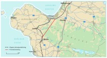
The overall Citytunnel Malmö project consists of 17 km of electrified railway lines and
3 new stations (Fig. 1). The individual projects are:
■ 6 km of tunnel below Malmö Central
■ 5 km of tracks above ground between the southern end and the Öresund Line
■ 6 km of tracks above ground directing towards Ystad and Trelleborg
■ Malmö Central main station
■ Triangeln Station
■ Hyllie Station.
Hyllie Station
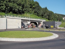
Hyllie Station is scheduled to be completed in 2011 in order to establish a commuter and transportation line to the new residential and commercial area that is developing in the south of Malmö. Once finished it will only take some 5 min to reach Malmö Central. Copenhagen Airport will be accessible in 15 min basically. Hyllie Station largely consists of 2 platforms each 350 m in length, which are being produced by cut-and-cover approx. 7 m below the surface. Above ground an approx. 50 x 180 m structure is erected.
Project Requirements
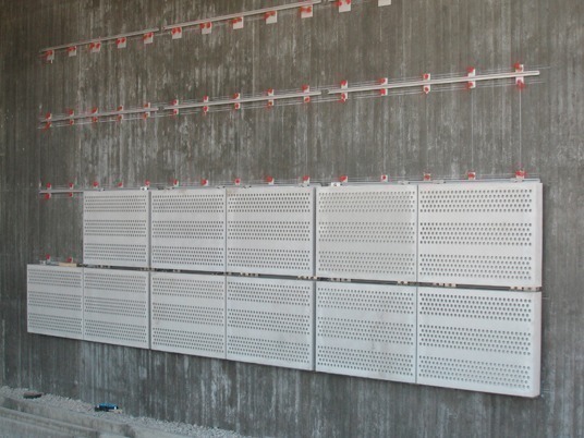
A wall cladding with sound absorbing panels is planned for Hyllie Station. Therefor an assembly substructure was sought, which can be subjected to dynamic stress and assured speedy assembly and disassembly of the cladding. The dynamic stress results from tensile and pressure load on the wall cladding caused by passing rail traffic.
Substructure for the Sound Absorbing Panels
A Halfen channel system consisting of hot-rolled assembly channels Type HM 40/22 and special hook bolts Type HS 40/22 was chosen as the substructure (Figs. 2 and 3) for attaching the absorber panels. The assembly channels were fully welded on to steel panels to attach the rail system on to the concrete subsurface and fixed to it using special dowels for dynamic loading.
General Conclusions relating to dynamic Strength (Fatigue)
In case of frequent load re-petitions, structural failure occurs at a lower level than for singular static loading. This phenomenon is known as fatigue. In 1863 August Wöhler detected through experimental analysis, that “the differences of stresses primarily cause premature fatigue”. Until today it still has not been possible to carry out reliable dimensioning on the basis of theoretical models for many structural systems. As a result it is still essential nowadays to execute fatigue tests in order to be in a position to draw fatigue curves or Wöhler curves as they are also known.
Dynamic Loading of the Substructure
The required dynamic resistance was specified by the structural engineer. A minimum number of cycles to failure of 3.3 mill. load cycles given a pulsating tensile stress as reference load of 2.0 kN had to be proven. Anchor channel profiles from Halfen are suitable to accommodate dynamic loads and are officially approved of. However other test parameters as for this particular construction project were selected for the approval tests. Thus the allowable range was established under extremely high static loads given a maximum vibration cycle number of 2.0 mill. The basic parameters of the possible resistances in accordance with the approval and the required limit state thus differ greatly from one another so that it is not possible to obtain proof on the basis of approval by the construction supervisory authorities. For this reason lab tests were conducted, which confirm the required resistance under the given requirements. Halfen’s stainless steel channel profile 40/22 was chosen.
Oscillation Tests
The tests were prepared and carried out by the HALFEN GmbH’s Research and Develop-ment department. Testing was conducted on a calibrated universal servo hydraulic test machine (Type Innova) with a maximum permissible testing load of 63 kN. The rail profiles used for the tests were taken from a defined batch with material test certificate 3.1 (according to EN 10204). The material supplied to Malmö also came from this batch.
The test samples were clamped in the test machine’s through special adapters.
These adapters were made of very stiff steel panels, which were connected with the test samples via bolts and simulating the punctual load distributions from the cladding. The lower load acceptance area provided the connection by means of 2 high-tensile M12 bolts (tightening torque 80 Nm) in order to represent the dowelled form of fixture. In the upper load acceptance area the connection was executed by means of 2 hook bolts (HS 40/22-M16,
A4-50 with a tightening torque of 60 Nm), which were to bear the absorber panels in their subsequent final state.
The tests took place at a frequency of 15 Hz and the load was applied in the form of a pulsating tensile load. The observed failure mechanisms were either a localised fracture in the channel lip area or a fracture caused by the entire channel profile. As expected no abnormalities could be detected on the continuous welding seam, the welded steel panel and the bolts.
Test Evaluation
The evaluations of the aforementioned tests confirmed without restriction the required permissible stress range of ΔF > 2 kN given a defined number of load cycles of 3.3. mill. The tests were analysed in accordance with 2 recognised methods:
■ In accordance with EC3 (ENV 1983) with a safety factor of 1.35 and against a 5 % fractile given a 95 % probability of statement
■ In accordance with SVA “Anchor Rails and Dowels”, with a safety factor of 1.5 and against a 10 % fractile given a 90 % probability of statement.
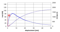
The result for the maximum determined stress range with regard to the 2 abovementioned verification methods varied between 3.26 and 3.49 kN (taking into account the partial safety factors). On the basis of the results Halfen was able to confirm that the planned special design complied with the requirements and can be executed as planned.
Conclusion
Thanks to the joint collaboration between the planning office, responsible contractor and Halfen it was possible to come up with a safe and flexible solution for fixing the absorber panels under the effect of dynamic loading. The project-specific requirements on the dynamic strength of the substructure for the cladding in Hyllie Station could be successfully proven through the aforementioned tests (Fig. 4).
Solutions provided from a single source are helpful especially for technically sophisticated issues as can be found in this project. Halfen was able to meet the demands of the project through the technical support of its own user-oriented International Compe-tenceCenter Technology (ICT) and Research and Development department (R&D) in cooperation with the planning office and the responsible contractor accurately and according to schedule.