Adalsbanan in Sweden
The Adalsbanan is a part of the plan decided on by the EU to standardise trans-border rail links in Europe (ERTMS European Rail Traffic Management System). In this connection Sweden is the first country in Europe to implement this plan at regional traffic level. Realisation is scheduled for 2030 and embraces both upgrading as well as the construction of new routes for Sweden’s railway system.
Adalsbanan and Bothniabanan
North Sweden’s link to the south has been substantially improved along the country’s eastern coastline thanks to the development of the railway infrastructure. The Adal and Bothnia Lines represent a part of this development plan. Thus along the Norrland Baltic Sea coast in future 50 to 60 trains per day will run instead of the present 8 to 10 and connect the important industrial locations in Sweden’s north-east with the south and above all, with the capital Stockholm.
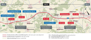
The altogether 180 km long Adal Line runs from Sundsvall via Langsele, Timra Härnsönd to Kramfors. There it connects with the Bothnia Line in the northern sector of the east coast link. In the course of the extension programme roughly 100 km of the Adalsbanan will be upgraded and a 30 km new section built. Eight new tunnels (including the longest: the around 4.5 km Kroksberg Tunnel), 16 railway bridges (including the longest: running 785 m over the Alands-fjärden) and 14 stations are to be produced. The extended Adalsbanan is scheduled to start operating in 2011.
To the north of Kramfors the 190 km long Bothnia Line runs from Angermanälven to Umea located in the north. It includes roughly 25 km in 16 tunnels with the 6 km long Namntal Tunnel, which was broken through back in 2007. The Bothniabanan represents one of Sweden’s biggest railway projects particularly on account of the 143 bridges (the highest is the 40 m high Nätraan Bridge and the longest the 1,937 m Umeälven Bridge) and the 22 stations. It is scheduled to be opened in August 2010.
Kroksberg, Bjässholm, Hallberg and Snaraberg Tunnels
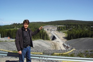
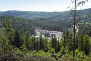
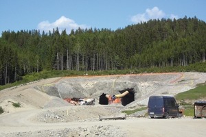
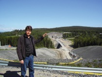
In the following a number of tunnels have been selected as examples for presentation alongside conventional driving as was practised there by means of ultra-modern drill+blast technology with the application of machinery. The responsible contractor is the Lemminkäinen Infra Oy, one of the oldest and biggest Finnish construction firms. Tunnel met up with Kari J. Korhonen, regional director for rock construction on site (Fig. 1). The 4.55 km Kroksberg Tunnel (Fig. 2) – the longest – and the Bjässholm (Fig. 1), Hallberg and Snaraberg Tunnels (Fig. 3) running south to north on the Bothniabanan are described.
General Description of Project
The Snaraberg Tunnel is 2,400 m long. Two service and evacuation tunnels have also been set up, each of which is 1,000 m long. The Hallberg Tun-nel is 800 m long but there is no evacuation tunnel as the greatest distance from the tunnel entrance is 400 m in each case. The excavated crosssections are similar to those of the Kroksberg Tunnel.
The pronouncedly changing geology, which belongs to rock classes 4 and 5 roughly in the southern sector of the Snaraberg Tunnel and classes 1 and 2 in the northern part. All featuring in the same excavation.
In March 2007 work commenced in the Kroksberg Tunnel with the setting up of the construction site and the production of the portal. At the end of May blasting operations started on the 2 roughly 260 m long access tunnels, whose excavated cross-section amounts to about 60 m². The gradient of the access tunnels amounts to 1:7.
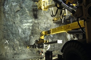
Work on the Snaraberg Tunnel began in the north in October 2008 and first in November 2008 in the south on account of the tricky subsurface conditions. Whereas in the north with rock class 1 the drill+blast drive for the service and main tunnels progressed well with 60 m/week given 7 shifts/week and 5.5 work days, only half the rate of advance was attained in the south. In the north with rock class 1 the length of advance amounted to 5.8 m with a drill hole depth of 6.2 m. On the other hand in the south lengths of advance of 3 m given a 3.2m drill hole depth were only possible on account of rock classes 4 to 5 (Fig. 4). Instable rock formations made progress more difficult and called for a greater quantity of shotcrete. This problem complex was mastered through an advance support using 6 m long forepoling spiles with 32 mm diameter. In keeping with the monocoque tunnel construction method without inner shell the drive was supported by advance grouting work. This served in the first place to seal the tunnel but it was also applied to secure the rock in tricky formations. Excavation work was completed in 2009 and in 2010 both tunnels, the Hallberg and Snaraberg were put into service.
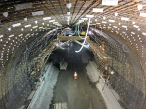
The 4,527 m Kroksberg Tunnel is the longest for the Adalsbanan project. The maximum tunnel overburden amounts to 70 m. The entire route including the tunnels is single-track and trains only halt at certain spots until oncoming traffic passes and the route is free.
The cross-sections in the main tunnel are equally large. However, special provisions and installations are required in the tunnel portal zones in order to secure them against frost. These apply for some 200 m into the tunnel in the north and roughly 500 m in the south. As a result the excavated cross-section in these entrance zones amounts to around 75.8 m². The main
tunnel has an excavated cross-section of roughly 70.3 m².
20 m long safety or evacuation tunnels are set up every 500 m, which possess an around 25 m² cross-section. They are linked with the service tunnel. There is an approx. 4,038 m long service tunnel with a 31.1 m² cross-section and a roughly 260 m access tunnel set up parallel some 20 m away from the main tunnel. In addition there are 2 other access tunnels in the middle (after roughly 2 km from the south) and on the southern side at the start of the Kroksberg Tunnel some 500 m away. The cross-sections of the evacuation tunnels are dimensioned in such a way that the tunnels can be negotiated with mobile rescue equipment. The final shotcrete support is basically executed by applying steel fibre reinforced shotcrete with an anchoring system.
The excavated volume amounts to about 465,000 m³ of solid rock. This excavated material is sold by the client for use as fill for road and railway construction.
The Kroksberg Tunnel is due to be completed in the course of 2010 and then made operational.
Geology
Prior to construction work the geology was investigated by means of core drilling and then the geological profile for the tendering documents established. During the drive it was however revealed that excavation class 3 mainly prevailed rather than class 1 as had been forecast. This called for considerably more outlay on shotcrete supporting and for substantially more rock anchors to be used, namely 72,000 rather than 27,000 (3 m long mortared permanent anchors with round anchor plate, roughly 25 cm diameter).
Inflowing water of 10 l per 100 m of tunnel from both tunnels (service and main tunnels) was permitted by the invitation to tender. In fault zones a maximum of 300 to 400 l/min of water prevailed only during the driving operations. The largest amount of water flowing from the tunnel however consisted of water for flushing the hammer drills needed for drilling operations.
Application of Construction Machines
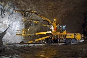
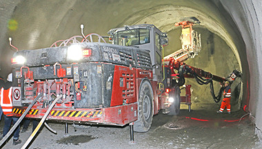
The reliable application of the construction machines is imperative for such an extensive project as the Adalsbanan. Two Boomer XL 4 C 30 with 4 COP 3038 hammer drills with 30 kW impact rate were deployed. Both drilling rigs are equipped with the Atlas Copco ABC Total control system. This enables a fully automatic drilling cycle to take place in accordance with a prescribed drilling pattern. One Boomer E 3 C 30 with 2 drilling arms and a service platform with COP 3038 hammer drills was also deployed. The blast holes are drilled each with 54 mm diameter. Each drilling arm was fitted with a rod magazine for extension drilling. Using this technique all types of drilling operations could be accomplished from the cab. The drill hole depth amounted to 24 m and the drill hole diameter
64 mm. A maximum of 36 drill holes were drilled over the entire tunnel profile including the floor. The drilling screen and the entire profile around it were drilled and in each case a 6 m overlap over a length of 24 m foreseen. Advance grouting was carried out after 3 lengths of advance. Given normal conditions some 15 drill holes between 10 and 14 hundred hours sufficed. During the grouting programme the data relating to the surrounding rock could be collected by the MWD system integrated in the drilling rig and used for advance exploration purposes (Fig. 5).
Smaller drilling rigs were used for anchoring. The 3 m long anchors possessed a diameter of 25 mm.
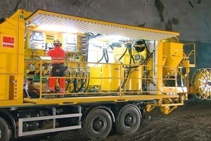
Grouting was undertaken by means of 2 grouting units – Type Unigrout Max 244 mounted on trucks – in each case using 4 grouting lines (Fig. 6).
Disposing of the Spoil
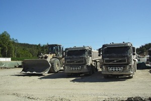
Subcontractors were employed to remove the excavated material with a Liebherr wheel loader, load it on to trucks and transport it from the tunnel. In the south and at the centre of the access tunnel
6 Finnish Sisu trucks R500 (modified roadworthy trucks with 4 and 5 axles) with 23 m³ loading capacity and a CAT loader 980G were used for this purpose. In the north 4 to 5 T30 dumpers and T220 dumper loaders from Volvo were employed. All loaders are fitted with a side-tipping bucket with 5 m³ bucket volume. This is highly advantageous for fast loading in the roughly 10 m high tunnel. The scaling operations were undertaken with special excavators and enjoy the utmost priority for ensuring safety during the drive (Fig. 7).
The time-critical factor in conventional tunnelling is loading and transporting the spoil. Thanks to the applied equipment around 200 m³ of spoil is loaded and transported per hour. Seen realistically 3.5 lengths of advance can be achieved per day by dint of a higher loading and transporting rate. This is the equivalent of some 20 m per day. The driving rate in the Kroksberg Tunnel and Bjässholm Tunnel together amounted to approx. 300 m per week under normal circumstances.
Shotcrete
The shotcreting operations were undertaken with Meyco and AMV equipment. Roughly 25,000 m³ of wet shotcrete was placed in the Kroksberg Tunnel until the end of June 2009. The shotcrete was produced on the spot by the contractor’s own mixing appliances, which provided some 44,300 m³ of shotcrete for no less than 4 tunnel projects by the end of June 2009. A modified shotcrete (concrete admixture Penetron Admix), which considerably reduced water permeability, was used to seal the tunnels.
Blasting Technology
The blasting technology is especially sophisticated. In the southern part of the Snaraberg Tunnel cartridged explosives were initially used on account of the difficult rock conditions. Normet explosives loading vehicles were employed. In the Hallberg Tunnel on account of the special geological conditions an explosives loading vehicle with 2 loading lines and 2 service platforms for applying emulsions with booster cartridges and Nonel igniters was used (Forcit Explosives). Both loading platforms were fitted with an automatic hose rewind system. This system enables the amount of explosive to be reduced especially in the trim holes, e.g. by 50 % to ensure gentle treatment of the rock and to avoid overbreak.
The specific outlay on explosives amounted to roughly 2 kg/m³ of solid rock in the main bore for the Hallberg Tunnel and in the north of the service heading for the Snaraberg Tunnel.
In the south of the Snaraberg Tunnel cartridged explosives with 17 mm diameter (for blasting the profile) extending up to 39 mm (for normal blast holes) given cartridge lengths of 1 m had to be applied on account of the geological conditions (rock classes 4 and 5) and instable drill holes. Blasting took place 3 times per day both in the north and south.
In the rock class 1 zones 3 lengths of advance were attained by 2 shifts and 2 drives. Four persons were involved: a drilling rig operator, 2 persons for blasting work and 1 service man. In other words, 3 lengths of advance each of 5.8 m were possible with a drilling and blasting crew. A 6 to 7 man strong labour force supplied by a sub-contractor was involved in loading and removing the spoil.
Explosives emulsions are increasingly being used for reasons of safety and technical application in drill+blast, as there is no need for complex storage and they are easier to handle.
Ventilation was supplied by means of a special blowing air supply, which amounted to 50 m³ of air/sec on average. The quality of the spent air was measured continuously.
Construction Costs
The costs for the Hallberg Tunnel and Snaraberg Tunnel amounted to around 40 mill. euros. The costs for the Kroks-berg Tunnel and Bjässholm Tun-nel were about 100 mill. euros.
Atlas Copco Craelius AB
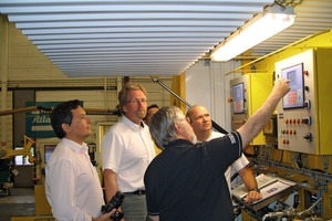
After visit the construction sites tunnel had the opportunity of becoming familiar with the various methods of grouting technology developed at Atlas Copco Craelius AB. Unfortunately so much detailed information was supplied that it is scarcely possible to reproduce this in summarised form. A tour of the production facilities with details of the latest grouting systems rounded off the visit (Fig. 8).

