Non-destructive Determining of the Thickness of Tunnel Inner Shells: Findings
This report presents recognitions gained so far through the application of the non-destructive testing of tunnel inner shells for a number of tunnels. In this connection shortfalls in the intended shell thickness determined on the various construction sites are comprehensively presented and evaluated. It is evident that the influence of the direction of concreting is of major significance for possible defects on the inner shell.
1 Problem
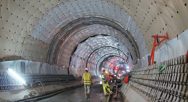
Tunnels are often produced in accordance with the shotcrete construction method. Following the completion of the outer shell using a temporary support made of shotcrete generally speaking an inner shell consisting of reinforced concrete is installed. The 2-shell method of construction offers among other things the possibility to install a plastic sealing membrane (KDB) between the inner and outer shell against hydrostatic load in order to secure the sealing function.
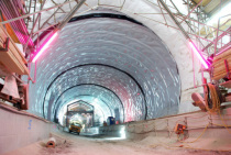
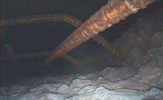
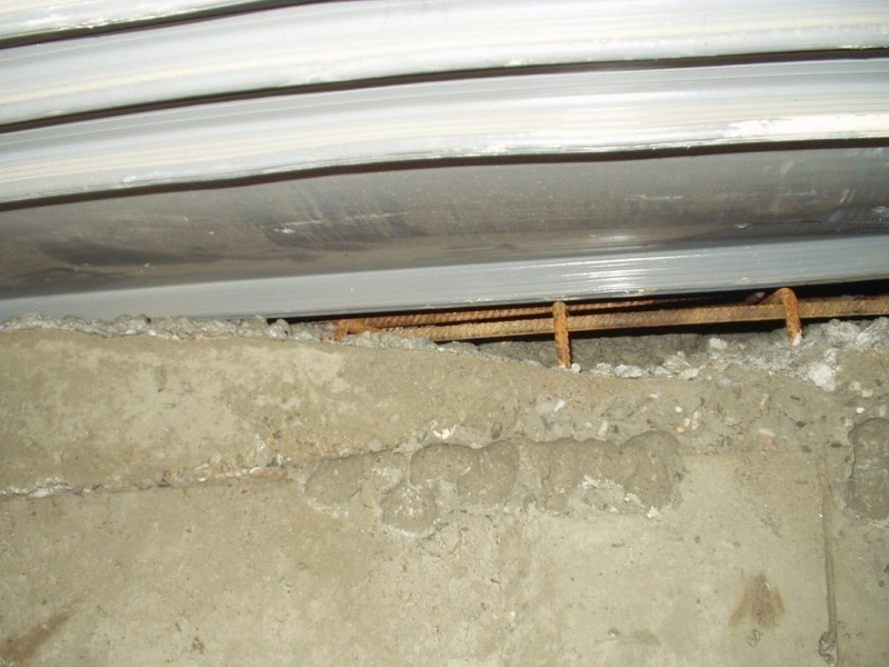
Should the intended shell thickness be inadequate the bearing capacity of the tunnel inner shell can be diminished and the functioning of the sealing system can no longer be assured. A hydrostatic load can bring about damage to the sealing system. In such a case the seal is pressed into the exposed reinforcement (Fig. 1) at the outer side so that the KDB is perforated thus causing leaks [1].
Fig. 1 displays 2 defects in the roof zone of a tunnel inner shell with exposed reinforcement. For a long time now non-destructive methods have been used to determine the shell thickness to localise such defects. In this way it is possible during the construction phase to draw conclusions relating to existing defects on the inner shell and repair them [2, 3, 4]. This procedure is regulated in the case of road tunnels as part of national trunk roads within the framework of the Guideline for the Application of the non-destructive Testing of the Tunnel Inner Shell (RI-ZFP-TU) [5]. This report presents the findings so far obtained during the production of tunnel inner shells on various construction sites using non-destructive testing methods.
2 Influence of Direction of Concreting
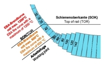
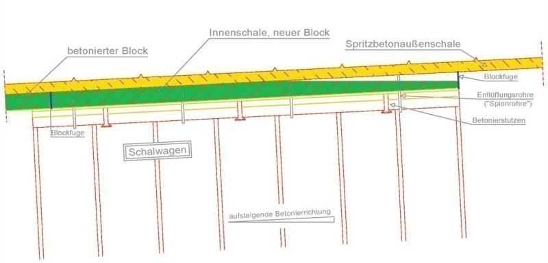
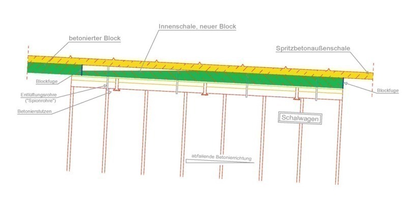
In the following the influence of the direction of concreting on the quality of execution is presented. Within the scope of the evaluating of non-destructive thickness measurements on various tunnelling sites it emerged that in many cases the intended shell thickness was not attained at the highest points in the block. Figs. 2 + 3 display errors that explain the described state of affairs in the simplified presentation of a longitudinal section through a tunnel section during the concreting process. Towards this end a block that still has to be concreted is presented together with an already concreted tunnel block.
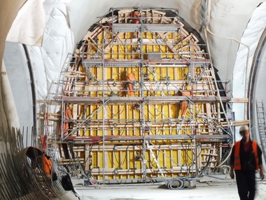
During the production of a tunnel inner shell a certain difference in height is bridged over between the beginning and end of the tunnel. 2 cases can be identified regarding the difference in height during the production process. Tunnels can be produced either in a dipping or rising direction of concreting. This results in the following problem complex for concreting the inner shell: there is the possibility that voids occur at the highest point of the tunnel block should the concreting process not be properly monitored. Monitoring the concreting process is carried out via so-called “inspection windows” at the stopend formwork as well as via “inspection pipes” on the formwork car along the roof. For example Fig. 3 shows that in the case of a dipping direction of concreting there is generally speaking no possibility of obtaining a visual indication of the concreting progress through the stopend formwork. As a result no conclusion can be drawn on whether the tunnel inner shell is completely filled at the block’s highest point. Given a rising direction of concreting in keeping with Fig. 2 the highest point is located within the range of the stopend formwork and can only be controlled visually until shortly before the end of the concreting process.
3 Evaluations at various Tunnelling Sites
Prior to the start of measuring the inner shells a defined measurement grid in accordance with RI-ZFP-TU [5] (5 measurement lines in the roof zone, 2 measurement lines in each case at the block joint) was applied on the tunnel bearing area. In this way it was possible to compare the results of certain measurement points on the individual blocks examined on a tunnelling site. Through this comparison it became evident at which measurement points or areas of the inner shell defects occurred with a maximum shortfall in the intended shell thickness. The measurement point, which was responsible for the largest shortfall in the entire blocks, was sifted out. This procedure was adopted for each measurement point until it was possible to sum up the results for the entire area under investigation. The maximum shortfalls which were determined for the intended shell thicknesses for all blocks are displayed graphically in the presentations that follow. Different colours are used to present the reduced thicknesses that were measured. The investigation results for a number of the tunnelling sites that were examined are presented in the following.
3.1 Tunnel A
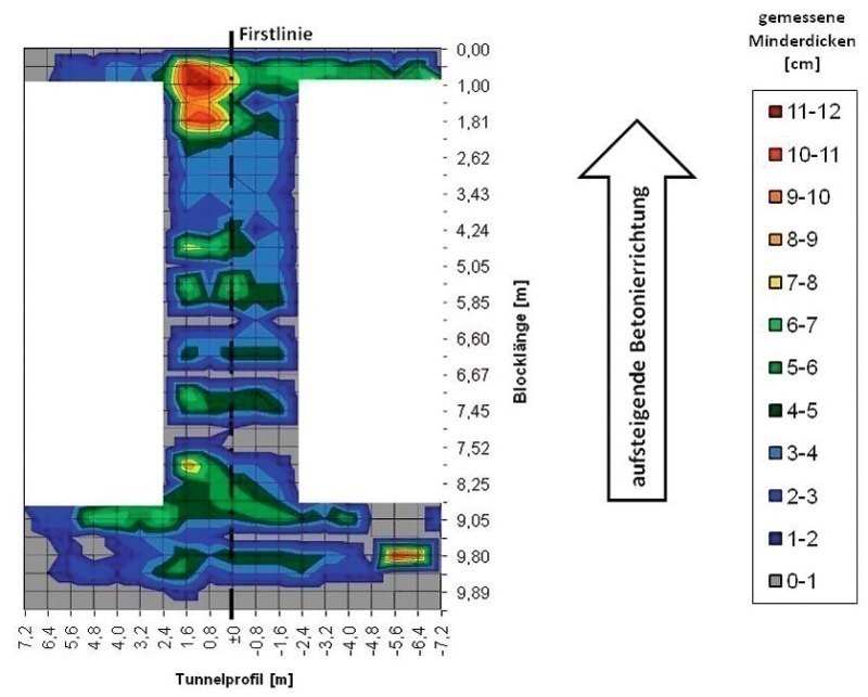
Altogether 176 blocks were investigated in Tunnel A. The tunnel inner shell was produced in a rising direction of concreting (Fig. 4).The intended shell thickness amounted to 35 to 50 cm. 55 of the examined blocks possessed a shortfall in the projected intended shell thickness (˜ 31 %). 121 blocks had no shortfall. Fig. 4 displays partial reduced thicknesses (extending over < 4 measurement points, measurement grid 80 x 80 cm) of 1 to 12 cm. The large-area reduced thicknesses concentrate on the roof as well as the area along the block joint. At the block joint (measurement grid block length 0.20 to 1.00 m) reduced thicknesses of up to 12 cm were registered. This corresponds to the maximum deviation of the intended shell thickness, which was not determined in any other measurement area. It can be assumed that in the case of such reduced thicknesses the reinforcement is exposed, as is shown in Fig. 1. The influence of a rising direction of concreting in accordance with the presentation in Fig. 2 is discernible. After closing the stopend formwork on the formwork car it is not always possible to check with absolute certainty whether filling has been completed.
3.2 Tunnel B
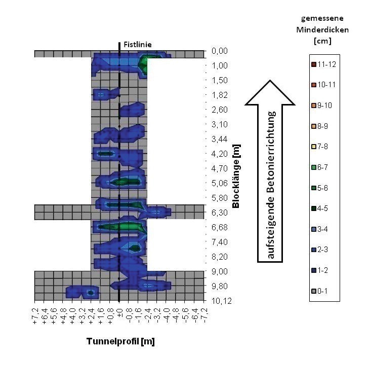
In Tunnel B (Fig. 5) a total of 178 blocks were investigated. The tunnel inner shell was produced in a rising direction of concreting. 22 of the examined blocks possessed a shortfall in the intended shell thickness (˜ 12 %). Tunnel B was produced on the same construction site as Tunnel A – with a short time delay. Compared with Tunnel A there are fewer defects given the same general conditions; work here took place with a different concreting team. It is shown that the quality of the execution also largely depends on the work of the crew and their qualifications. An influence exerted by the direction of concreting is also discernible here although not to the same extent as in the case of Tunnel A. The reduced thicknesses amount to between 1 and 7 cm. With regard to the area distribution it can be ascertained that mainly small-area reduced thicknesses (extending over 20 to 4 measurement points, measurement grid 80 x 80 cm) were measured.
3.3 Tunnel C
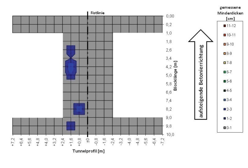
In Tunnel C (Fig. 6) 10 blocks with an intended shell thickness of 40 cm and 21 blocks with an intended shell thickness of 50 cm were evaluated. 3 of the examined blocks possessed a shortfall in the intended shell thickness (˜ 10 %). No shortfall was registered in the case of 28 blocks. Fig. 6 displays individual and small-area reduced thicknesses. The maximum shortfalls amount to roughly between 3 and 4 cm. Given such conditions it can be assumed that the reinforcement is completely embedded in the concrete in the roof zone providing that the reinforcement is positioned correctly.
3.4 Tunnel D
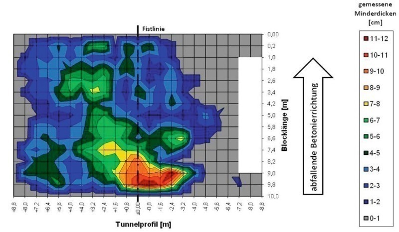
Large-area investigations to determine the thickness areas of the tunnel inner shell were undertaken on Tunnel D. A total of 40 blocks were checked, in the case of 35 blocks a shortfall in the intended shell thickness was established (˜ 88 %). No reduced thicknesses were registered in the case of 5 blocks.
The intended shell thickness amounted to 40 cm in the case of all examined blocks; the block length amounted to 10.00 m. The graphic presentation in Fig. 7 makes it evident that reduced thicknesses of the inner shell were recorded at practically every investigated measurement point in the roof zone. The shortfalls of the intended thickness range from 1 to 12 cm, with the maximum deviation of the intended shell thickness of 12 cm appearing over a large area at the block joint connecting with the block already concreted. Given such reduced thicknesses it can be assumed that the reinforcement is exposed, as presented in Fig. 1.
The influence of a dipping direction of concreting in accordance with Fig. 3 is evident. As a result of the difference in height within a block, which can amount to several decimetres, it is not possible for the concreting team to properly control the complete filling of the tunnel shell in the roof zone.
3.5 Tunnel E
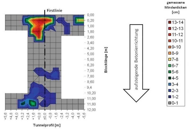
At places large-area defects are discernible in Tunnel E (Fig. 8). Altogether 68 blocks were investigated, with a shortfall in the intended shell thickness of d = 35 cm (˜ 40 %) being recorded in the case of 27 blocks. Large-area reduced thicknesses of up to 14 cm were measured at the block joint. Exposed reinforcement in the roof zone was established by means of endoscopic recordings through apertures for the subsequent grouting of the roof gap. Tunnel E was produced in a rising direction of concreting (gradient of 2.5 %) in keeping with Fig. 2. As a consequence the position of the large-area defect is if anything unusual and was not foreseen in this form. However during the concreting of several blocks it could be observed that the pipes for subsequently grouting the roof gap were clogged up with concrete residues in this area of the formwork car. Thus probably an air bubble had formed at the defective area during the concreting stage, which prevented this area from being filled any further.
Table 1 presents the results of the evaluations undertaken so far on various tunnelling sites with regard to the maximum shortfall in the intended shell thickness, the slump as well as the frequency distribution in summary form.
4 Conclusion and Outlook
In the meantime far-ranging recognitions as well as data material are available for the non-destructive determination of the thickness of tunnel inner shells. In this report essential aspects regarding the frequency and the distribution of defects as well as shortfalls in the intended shell thickness are presented based on evaluations of these data. Furthermore the influence of the direction of concreting on the position and frequency of reduced thicknesses is displayed. Tunnel shells, which are produced in a dipping direction of concreting, show themselves to be especially susceptible to flaws in this respect.
It was shown that in the case of various tunnelling sites following the concreting phase that the reinforcement in the roof zone was probably exposed and was not completely embedded in the concrete. At the very worst this can lead to damage to the plastic sealing membrane and in turn to subsequent leaks in the sealing system.
As a result particular importance is attached to the subsequent roof gap grouting, which has to ensure that the reinforcement is completely embedded in the concrete. In the past the grouting material could not be properly identified on a number of construction sites with non-destructive test methods. To-wards this end in a BASt (Federal Highway Research Institute) research project [6] – on behalf of the Federal Ministry of Transport, Housing and Urban Develop-ment – undertaken at the Fachhochschule Münster this issue was investigated.
The evaluations with respect to shortfalls in the intended shell thickness reveal that it appears purposeful and necessary to record and check the shell thickness during the concreting stage. In this way complex and time-consuming repairs of defects can be avoided. Follow-up tests are currently being carried out at the Fachhochschule Münster in this field at present.