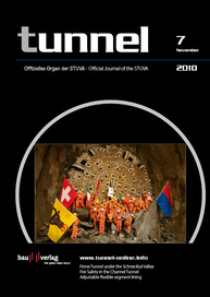
The Finne Tunnel under the Schnecktal valley
The passage under the Schnecktal valley (the Finne Tunnel), a key element of the new „VDE“ (German Reunification Transport Infrastructure Project) 8.2 line between Erfurt and Halle/Leipzig, impinged on a highly ecologically sensitive geographical feature. The following article examines in detail the planning and implementation of machine tunnelling with only minimal overburden cover.
1 Introduction
Despite the high present-day level of automation and mechanization, mechanized tunneling begins to encounter its limitations in shield-machine operations with no active rockface support and minimal overburden cover thicknesses of less than 0.5-fold the shield diameter.
The Finne Tunnel on the new VDE 8.2 line between Erfurt and Halle/Leipzig, designed for safety reasons as a twin-bore tunnel, was driven using two tunnel boring machines (TBMs). Tunneling under the ecologically sensitive “Schnecktal“ valley area was accomplished successfully, with a minimal cover of 4.5 m, in an environmentally acceptable manner and with little impact on the surface. Achievement of this feat was decisively assisted by the consistent implementation of a strategy specifically orientated around the shield-tunneling method, and which, from the planning stage onward, via the preparatory activities, up to and including implementation, was determined by the definition and continuous monitoring of the critical process and mechanical assessment parameters, on the basis of process controlling. The characteristic feature of this strategy is risk prevention, which is systematically implemented by means of special steering elements. These risk-prevention elements include contingency analyses, the TBM scope statement, the shield manual, machine inspection and process controlling, using the supporting tunneling previews and working procedures assigned.
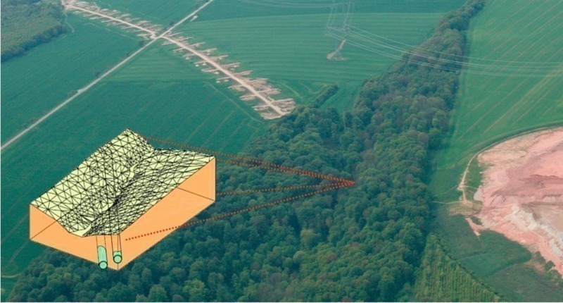
This article begins with an overview of the project in principle, and then examines the implementation of this strategy during the preparatory phase and the actual performance of shield tunneling, using the example of passage under the Schnecktal valley (Fig. 1).
2 Project overview
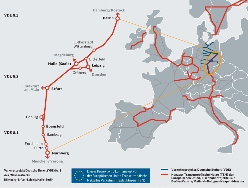
Verkehrsprojekt Deutsche Einheit (VDE = German Reunification Transport Infrastucture Project) No. 8 was initiated by Germany‘s federal government in 1991, a few months following reunification. Encompassing the upgrading or construction from new of some 500 km of line, it is the largest of the program‘s nine rail projects, and forms part of the overall portfolio of projects for expansion of the Trans-European transport infrastructure (Fig. 2).
The Finne Tunnel, at 6970 m the longest on the new VDE 8.2 section of line, was planned, for safety reasons, as a twin-bore tunnel, and passes on the eastern edge of the Thuringian Syncline under the towering Finne ridge on the fault of the same name. A critical element in the selection of the route was the passage of the line, necessary for ecological reasons, below the Schnecktal valley, with an overburden cover of only around 4.5 m. The planning of the tunnel also had to take into account the underground water level, which is, to a large extent, located up to 50 m above the tunnel bores.
In fulfilling these boundary conditions, the draft invitation to tender envisaged as the tunnelling concept parallel shield tunnelling using two shield-tunnelling machines and segmental support, proceeding from the tunnelling starting point in the west the tunnelling machines being required to drive the first 1547 m with a slurry-pressure supported face (hydroshield mode), and the subsequent 3095 m section up to the entry to the machine recovery cavern with no slurry-pressure supported face (open mode). Tunnelling in the opposite direction, using shotcreting methods and drill, blast and excavate tunnelling, with subsequent installation of the interior tunnel lining, was planned from the eastern portal.
The contract for the entire Finne Tunnel project was awarded by DB Netze AG, represented by DB ProjektBau GmbH, Leip-zig, in December 2006 to the „Arge Finnetunnel“ (Finne Tunnel Consortium), consisting of Wayss & Freytag Ingenieur-bau AG, Frankfurt am Main, Max Bögl Bauunternehmung GmbH & Co. KG, Munich,Porr Technobau und Umwelt GmbH, Munich, and Porr Tunnelbau GmbH, Vienna.
The consortium was obliged after start of contract to modify the technology envisaged for the tunnelling concept as a result of changed boundary conditions. The changed tunnelling concept dispensed with conventional simultaneous tunnelling from the opposite direc-
tion and extended the shield tunnelling sections to include the complete length of the tunnel up to the eastern portal.
The zone below the Schnecktal valley was, as a conse-quence, therefore also to be driven using the tunnelling machines.
3 Geotechnical and hydrological conditions
3.1 Overview
In the Finne Tunnel sector of the works, the new rail line crosses the transition line from the Thuringian Basin to the, in comparison, elevated structure of the Hermundurian Massif. These two features are separated from one another by the Finne fault zone, running approximately north-west to south-east.
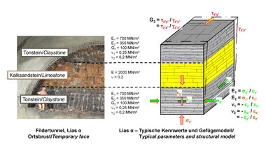
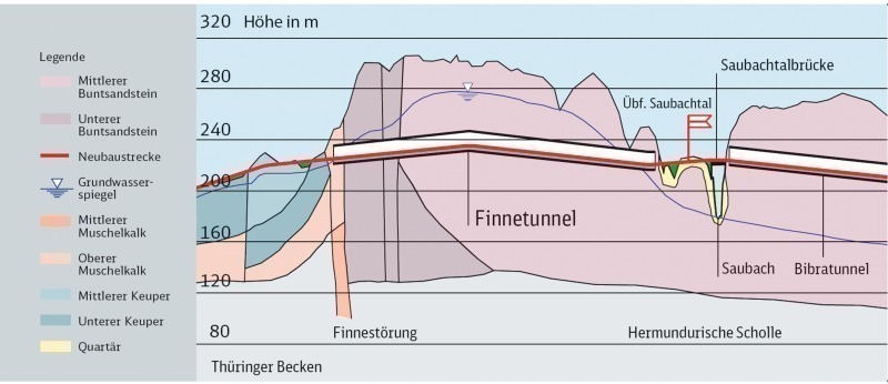
The following geological sequence thus resulted for the Finne Tunnel, the entire length of which traverses the Triassic formations: the western entry length encountered approx. 300 m of Muschelkalk [1] and Upper Triassic, followed by some 650 m in the Lower Triassic, and around 5900 m in the Middle Bunter. The alternating sequence of marlstone, limestone, siltstone, sandstone and mudstones was heavily influenced by the Finne fault along the first 1500 m of the tunnel route (Fig. 3).
In the vicinity of the Finne Tunnel, the groundwater table rises continuously from the west, and is at many points at a maximum of around 50 m above the roof of the tunnel. To the east of the Steinbachtal valley, the groundwater table falls toward the Saubachtal valley, with the result that the eastern sector of the Finne Tunnel is located above the groundwater table.
3.2 Preliminary exploratory work in and around the Schnecktal valley
The Schnecktal valley is located in the sector of the route in the Middle Bunter. The tunnel bores pass at a glancing angle under the valley formation, which is characterized by relatively steep embankment slopes on both sides (Fig. 1).
Geological conditions here are characterized in the geological appraisals by quaternary loams present in the immediately sub-surface zone, and Middle Bunter strata below them, with a weathering horizon of a thickness of at least 1 to 2 m.
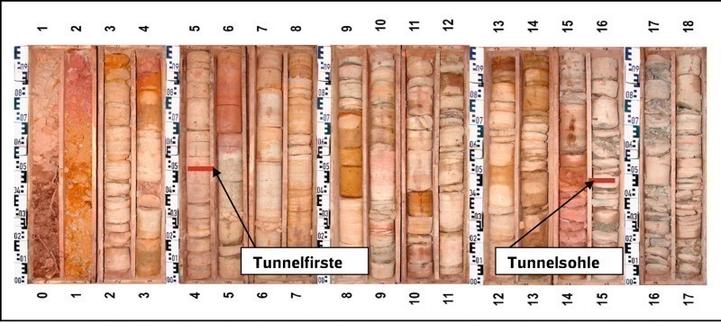
This geological data was of sufficient accuracy for the shotcrete tunnelling method specified in the invitation to tender, in combination with the contractually agreed preceding support by means of pipe arches, but not for machine tunneling. Further cores were therefore drilled in the immediate zone of the valley, as preparation for mechanical tunnelling operations (Fig. 4).
The results of this supplementary exploratory program can be summarized as follows:
Around 1.5 to 2.6 m of the northern bore of the tunnel passes below the weakened to disintegrated weathered zone of the bunter sandstone rock. The tunnel roof and around 50% of the excavation cross-section are located in a sequence of strata of predominantly poor to moderate coherence.
The southern bore of the tunnel runs in some zones immediately below the weakened to disintegrated weathering horizon, with sediments of little strength, possessing predominantly only poor to moderate coherence, in the upper zone of the excavation cross-section.
Crumbling of the tunnel roof, and/or falls, must be anticipated in the roof zones of both bores, and in the southern bore, in particular, due to only slight overburden cover and pre-dominantly low-strength sediments.
The geological conditions can, in addition, be characterized in terms of shallow stratigraphic conditions in the bunter sandstone rock, and steep joint planes.
Coherence in the lower zones of the cross-section is predominantly good and rock strength is better; isolated siltstone inclusions of low thickness occur.
4 Shield-machine tunnelling method
As outlined above, the original plan, in view of the geological and hydrological boundary conditions, and of the possibility of lowering the groundwater table only in some instances, envisaged subdivision of the shield tunnelling section as a whole into individual sectors with and without a slurry-pressure supported rock face.
The first approx. 1500 m were therefore driven using the so-called closed mode with a slurry-pressure supported face. Following this sector, the face was sufficiently stable, and the ingress of water sufficiently controllable, with the result that it was possible to dispense with active rock-face support and complete this sector using the open-mode method. The rest of the section was therefore driven, after conversion of the shield-tunnelling machines, using open mode, with no active rock-face support.
The invitation to tender had taken as its aim the deployment for the tunneling work of a shield-tunneling machine which would provide sufficient potentials for the overcoming, as rapidly and safely as possible, of the worksite, methodological and mechanical problems predicted for the tunnelling operations, in order to achieve unhindered and trouble-free tunneling and completion. For this purpose, the invitation to tender envisaged special mechanical requirements for mastery of the geological boundary conditions and the demands made by the working environment; these were compiled in the invitation to tender in a separate requirement profile for the shield-tunnelling machine.
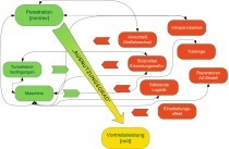
The requirement for a contingency analysis for critical tunneling situations was a further element in the invitation-to-tender documentation. The contractor was to use this contingency analysis to study and familiarize himself with all foreseeable geological, methodological, mechanical and working-environmental contingencies and potential complications for the tunneling operations, in order that the knowledge thus gained could be incorporated into the conception and design of the shield-tunnelling machines.
The contingency analysis was conceived, in line with the philosophy of risk prevention, with the aim of preventing the occurrence of the consequences of the particular contingency. The design provisions implemented in the machine concept acted in this context as preventative measures.
Supervisory and monitoring systems served the purpose of early advance recognition of each particular contingency scenario, on the basis of which provisions for overcoming of the contingency were defined even before the start of tunnelling operations.
In accordance with the strategy embodied in the invitation to tender, the following steering elements for the conception of the shield-tunnelling machine were also incorporated into the contract:
- Drafting of a scope statement for the design of the machine, in which the essential requirements for the machine are documented, complete with methodological and mechanical solutions;
- “Acceptance inspection“ of the shield-tunnelling machines at the manufacturer‘s works, complete with demonstration of the machines‘ essential functions;
- Drafting of a shield manual, including more specific definition of the mechanical and methodological monitoring parameters, for the purpose of sensitization of the tunneling crew.
The author intends to dispense here with a general description of the individual steps in this strategy and its implementation in the conception of the tunnel boring machines and the preparation of tunneling, and to draw attention, instead, to the relevant literature. The adaptation of the strategy is examined below solely taking account of the boundary conditions in and around the Schnecktal valley section resulting from adaptation of the technology.
It was necessary, in the context of conception of the TBM, not only to take account of the known geological boundary conditions and those disclosed in more detail by the additional program of exploration, but also, specifically, the requirement for only minimal subsidence, in order to avoid a collapse scenario, in view of the minimal overburden cover of only 4.5 m.
An essential requirement in order to meet the needs in this sector was the ability to create a grout curtain or pipe arch system in the roof zone for advance stabilization of the underground.
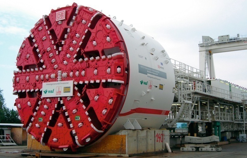
In accordance with the conditions of the invitation to tender, two convertible shield-tunneling machines (see table) were proposed and ordered for the works, and were supplied by Herrenknecht (Fig. 5).
The consortium‘s conception phase for the shield-tunneling machines was actively supported by the client and his advisors. In addition to the design of the shield-tunneling machines in conformity to the contractual conditions, the client, with assistance from his advisors, also submitted recommendations, the essential basic elements of which were also accepted and implemented by the contractor.
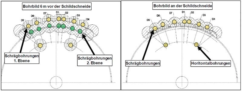
In line with the requirements, the TBMs were equipped for the Schnecktal valley section in such a way that both the performance of exploratory borings and of rock improvement provisions in the form of drilled and grouted bolts and/or a pipe arch were possible from the shield.
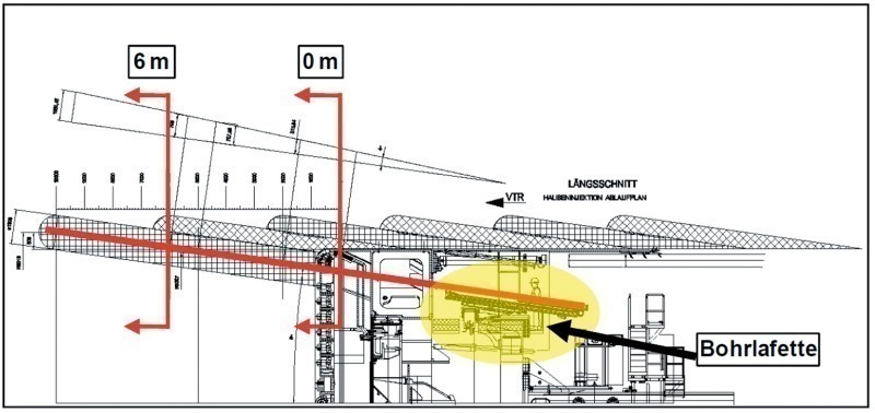
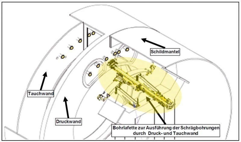
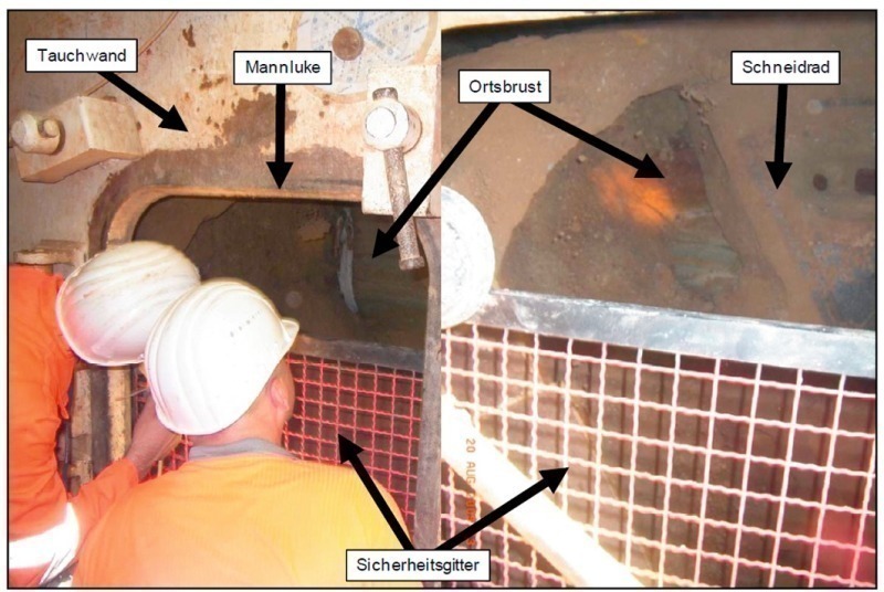
There was a facility to drill through the cutting wheel, by means of a drilling platform, via drilling ducts in the pressure bulkhead and/or immersion wall. These borings could be made both horizontally to the front and also at an inclination of 8 degrees (Fig. 6 to 8).
A further facility for drilling operations resulted from the use of drilling carriages which, mounted on erector-adapter plates, permitted the performance through the shield skin of radial inclined borings at an angle of approx. 10 degrees.
The suitability in principle for installation of the drilling unit and for the execution and feasibility of the grouting and pilot borings was proven in the context of the demonstrations during inspection of the tunneling machines at the manufacturer‘s works. The process of conception of the TBMs in accordance with the mechanical requirements in principle concluded with these function trials.
5 Mechanical and methodological concept for tunnelling under the Schnecktal valley
In accordance with the basic concept for the sequence of the works, tunneling in the southern bore was started only after completion of the hydroshield sector (1500 m) in the northern bore. This resulted in the northern tunneling operations in the Schnecktal valley sector, encountering less adverse boundary conditions, being completed around five months before the tunneling operations in the south bore. Knowledge gained from the first tunneling operation could therefore be incorporated into the preparatory activities for the more difficult operations for creation of the southern bore.
The consortium discovered during the preparatory work on the planning necessary for tunneling under the Schnecktal valley that the in-filling of the exploratory bore holes installed in 2007 had in some cases subsided. In order to eliminate any possibility of complications for the tunneling operations resulting from this circumstance, the contractor grouted the rock from the surface to a point just above the tunnel roof via grouting holes.
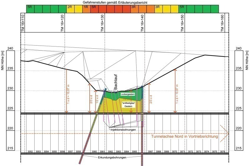
Zones critical for the tunneling operations, orientated, on the one hand, around the predicted rock quality and, on the other hand, around the prevailing overburden cover conditions, were defined in the execution planning for the tunneling concept. This classification into zones served the purpose of systematic categorization of tunneling operations, and was used as the basis for decisions concerning and definition of the use and scope of preventative rock improvement provisions.
Four zones were differentiated, and are highlighted in colour in Fig. 9 according to their risk potential on the basis of the ratio of soil cover to tunnel diameter.
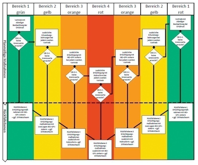
The various exploratory borings and rock improvement provisions which could be implemented from the TBM were also planned in detail during this phase and, in a further step, assigned to the tunneling zones already defined. The result was a grid on which both the planned activities and the fall-back levels allocated in case of deteriorating conditions are defined (Fig. 10).
The ultimate decision concerning the scope and implementation of the rock improvement provisions was to be made during tunneling operations, in response to the conditions encountered in-situ.
In addition to surveying and assessment of the geological conditions immediately at the rock face, and analysis and evaluation of the essential machine parameters, including assessment of the situation for bedding of the segmental support, surface subsidence was also a definitive criterion in the selection and stipulation of the appropriate countermeasures.
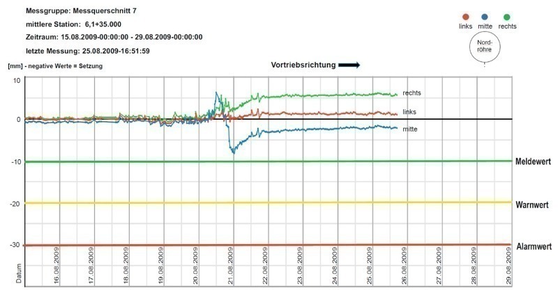
The deformation data were classified into reporting, warning and alarm values, in the form of so-called „intervention values“, which are directly linked, in case of their occurrence, to corresponding countermeasures to be implemented both from the surface and from underground.
It as necessary, on the basis of this fundamental concept, to define machine parameters, install a comprehensive monitoring program and draft working procedures, in order thus to be able to interlink the essential influencing factors with one another.
5.1 Machine provisions
The following machine provisions were defined for scheduled tunneling operations in the working procedures specifically tailored to creation of the tunnels under the Schnecktal valley:
- Implementation of an expanded-scope maintenance shut-down prior to tunneling under the Schnecktal valley, with the objective of avoiding machine-related stoppages of the TBMs in the critical zones;
- Reduction of the steering gap of the TBMs to the minimum technically necessary during the expanded-scope maintenance shut-down, by means of the installation of bore cutter disks with defined wear dimensions;
- Lubrication of the shield skin using viscous bentonite paste via radial grouting ports in the shield skin in extreme cases, in order to reduce friction in good time before the shield could become jammed;
- Installation of segmental support elements with an increased reinforcement content in order to counteract greater tunneling forces and any asymmetrical rock loads;
- Intensified monitoring and adjustment of the relevant machine data;
- Keeping of the distance between the rock face and the shield blade in general as small as possible during tunneling operations (minimum cutting wheel deviation);
- Continuous direct visual observation of the excavation operation via the hatch in the immersion wall;
- Stopping of tunneling operations and inspection of the rock face in case of visually ascertained excess excavation rates and/or of excess tonnage indicated on the belt weigher.
The following provisions were planned to permit mastery of any cases of instability, particularly in the roof zone:·In case of excavation of greater than 20 cm, tunneling would be continued, until the excess excavation was located at least 25 cm above the shield blade in the longitudinal direction. The cavity above the shield would then be filled with fast-setting silicate foam;
- In cases of instability of the rock face, the mining parameters for tunneling would firstly be adjusted (no rotation of the cutting wheel without tunneling, increase of thrust force and limitation of penetration).
5.2 The monitoring program
The tunneling operations were accompanied and supported by continuous monitoring of machine data and of the entire tunneling process. The data were permanently and completely recorded automatically, relayed on-line and in real time to the site management, the site supervision team, the client and his advisors, and also stored and archived on data-bearers.
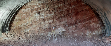
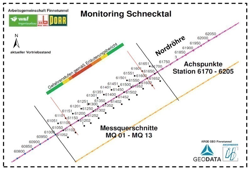
The data on deformations on the tunnel route, in conjunction with the observations of the rock face made via the hatch, permitted qualified verification of the tunneling parameters defined in advance, and were essentially used for assessment of the necessary adjustment of these parameters and, ultimately, of the necessary additional rock improvement and other provisions for stabilization of the tunnel route. Gauging sections were installed in the Schnecktal valley in the vicinity of the respective tunnel bores (Fig. 11) for determination of surface deformations, and were monitored throughout the periods of tunnelling.
An automatic measuring system (tacheometer) was installed in the Schnecktal valley for the purpose of continuous determination of the absolute deformations of the individual measuring points. The deformation data obtained were relayed, by means of electronic data interchange, via the site office to the crew on the tunnelling machine. In addition, a graphical evaluation of subsidence events was supplied to the critical persons and advisors on-line via the Internet. Continuous monitoring and assessment of the data, and short reaction times, were thus assured.
5.3 Working procedures
In addition to the shield manual, which lays out the methodological requirement profile for the shield-tunnelling campaign, including the implementation of the action defined in the contingency analysis, the working procedure pursues the aim of sensitizing the tunneling crew to recognize critical tunneling situations at an early stage and tackle them appropriately.
The in some cases complex and extensive documentation (work planning, tunneling preview, geological and geotechnical exploratory surveys, etc.) are here compressed and the essential activities relevant to tunneling operations made available to the tunneling crew.
The following parameters for shield-tunnelling operations in the vicinity of the Schnecktal valley were defined, inter alia, in the working procedure:
- Machine-setting parameters, including possible bandwidths (range) and parameters for data evaluation.
- Parameters for monitoring of mass balance; for visual observation of the rock face and evaluation of the measured subsidence data on the surface. Parameters for the surface observation personnel.
- Definition of work necessary for improvement of the rock face and/or tunnel walls
- Detailed instructions concerning the necessary behaviour and the necessary action in case of possible shield overcuts.
In addition, organizational charts, notification chains and shift timetables for the supervisory tunnelling personnel were also integrated into the working procedure, in order to delineate responsibilities clearly, and assure strict adherence to and implementation of the provisions defined.
6 Performance of tunnelling and analysis of tunnelling experience
Tunneling in the northern bore in the Schnecktal valley sector was performed in August, 2009, around five months ahead of the corresponding operations in the southern bore.
Geological conditions were monitored, on the one hand, by means of images of the rock face made during the breaks in tunneling operations for installation of segmental-ring support and, on the other hand, continuously by means of visual observation via the hatch, which was protected a metal grill (Fig. 12).
These geological surveys were supplemented during the first few meters of tunnelling under the Schnecktal valley (in the green and yellow sectors) by means of two exploratory bore holes through the cutting wheel in the direction of tunnelling advance. There were no indications of any potential irregularities.
In view of the favourable and profile-consistent geological conditions and the minimal incidents of subsidence on the surface, the tunnelling crew decided, in agreement with the client and his advisors, to dispense with additional rock improvement measures (drilled and grouted GRP anchor bolts and/or pipe arch system) implemented from the machine, in order to prevent interruptions to tunnelling operations as far as possible, to avoid disturbing the formation in the roof zone unnecessarily, and to assure the most continuous possible tunneling progress.
During further tunnelling operations, a slight increase in the degree of weathering of individual strata in the dark-red zone resulted, in combination with poor coherence, in crumbling of the roof. During installation of segmental support rings, silicate foam was applied via four rings to the wall and/or into the annular gap between the shield blade and the surrounding rock in order to reduce and, where possible, avoid such crumbling and provide support for the rock.
This procedure made it possible to tunnel under the critical sectors of the Schnecktal valley in the northern bore (56 m) within around 47 hours without the occurrence of any critical tunneling situations. The subsidence measured on the surface was predominantly significantly below the „warning figure“ of 10 mm, and was in most cases restored to the original elevation by means of pressure-grouting with mortar (Fig. 13).
The experience gained in the creation of the northern bore was evaluated during the review of the tunnelling operations, and also in a separate experience report, and was used for preparation and „fine-tuning“ of the tunnelling concept for the south bore.
It was possible only to a limited extent to apply the results achieved in the northern bore to the southern bore, due to the less favourable situation in the valley section and the weathered rock and non-coherent-rock horizons forecast to be extending into the roof zone in accordance with the exploratory bore holes made in 2007. In addition, reliable information concerning the rock improvement surmised as a result of filling of the exploratory bore holes was also lacking in the critical sectors. For this reason, an additional core was drilled in the vicinity of the tunnel roof for the purpose of further investigation of the actual conditions prevailing there, and in order to minimize risk.
This exploratory bore hole made it possible to assume soil improvement and a „solid-rock roof“ analogous to the northern bore above the crown of the tunnel.
The concept for creation of the southern bore in the Schnecktal valley zone was modified in accordance with the discoveries made and on the basis of the principle of performing rapid and continuous tunneling using the shield-machine in the critical sector. The decision grid in the working procedure was amended in such a way that additional rock improvement provisions from the TBM (drilled and grouted GRP bolts) were now no longer defined as a scheduled provision, but instead only as the fall-back level. These additional measures were to be initiated on the basis of assessment criteria defined in advance and in reaction to the „warning“ values assigned to them (incidents of subsidence and crumbling in the roof zone, in particular).
The personnel hierarchy of responsibilities was again intensified vis-à-vis the tunneling operations in the northern bore, in order to assure qualified assessment of the critical appraisal criteria and initiation of the resultant defined countermeasures. Additional grouting ports in the shield skin in the front section of the working chamber were installed on the south TBM in order to optimize application of the silicate foam in the roof zone between the shield skin and the rock. This made it possible, unlike the situation during the initial application while tunnelling using the northern TBM, to inject foam via a bent grouting lance not only during cutting wheel shut-downs, but also systematically, during tunnelling operation.
The southern TBM reached the underground Schnecktal valley zone in January of 2010. The geological conditions encountered there were comparable to those in the northern bore, and could even be classified, across large areas, as better. This was apparent, in particular, in the form of a reduced tendency to crumble. It was therefore possible to perform tunnelling in accordance with the finalized concept and essentially with no additional provisions and only minimal subsidence. No critical tunnelling situations occurred at any time, and it was possible to embed the segmental support shell as planned, and install it without damage.
The successful completion of tunnelling under the Schnecktal valley using the south TBM within a time window of around 70 hours for the 100 m of the critical sector was the result of intensive preparatory work and the constructive cooperation of all those involved.
7 Summary and prospects for future projects
The tunnelling concept used for the Finne Tunnel proved its value entirely, including the mastery of difficult operational situations. Both bores of the critical Schnecktal valley section were completed with maximum support quality, minimal subsidence and no problems. This success was definitively determined by the consistent implementation of the strategy described in this article. This strategy is therefore expressly recommended for use in future projects.