Transport-infrastructure Tunnels for the 2014 Winter Olympics in Sochi / RU
Sochi is the venue for the 2014 Winter Olympic Games. This article was a paper of the Swiss Tunnel Conference 2011 in Lucerne/CH and includes a project overview of the new transport link between the Olympic Village on the Black Sea coast and the winter-sports region in the Caucasus mountains. The article concludes with an examination of the tunnelling and support methods customary in Sochi, and their special features.
1 Introduction
The Russian city of Sochi is the venue selected for the Winter Olympics in 2014. The region extends for 145 km along the north-east coast of the Black Sea, at the foot of the Caucasus mountains. Sochi, with its sub-tropical climate, is one of Russia’s most popular sea and spa resorts. A major portion of the Olympic skiing events, including the Alpine skiing, ski-jumping and biathlon, are to be held in the mountains above the town, with their significantly lower winter temperatures. When the Winter Olympics close, Sochi is to be the host for the 2014 Russian Formula 1 Grand Prix, and one of the venues for the FIFA World Cup in 2018.
Not only the sports and athletics facilities, hotels, energy infrastructure, etc., but also the road and rail systems are being upgraded throughout the region around Sochi, by way of preparation for the 2014 Winter Olympics.
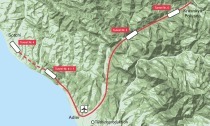
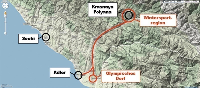
In addition to some 37 km of overpasses and bridges, more than 29 km of new tunnels are under construction between the town of Adler and the Krasnaya Polyana winter-sports region some 50 km distant in the Caucasus mountains (Figure 1). The route includes a total of 6 tunnel complexes (Table 1). This upgraded infrastructure will assure the shortest and most efficient possible access routes for visitors to the games. Work started in June, 2008; completion is scheduled for April, 2013.
The client for the entire infrastructure in and around Sochi is DCRC, a subsidiary of Russian Railways (RZhD). Only Russian enterprises are engaged on the construction of the new infrastructural facilities between Sochi and Krasnaya Polyana. The geologists and designers commissioned are also very largely made up of Russian companies.
2 Geological conditions
The basic geological structure of the region was determined by a number of cartographic campaigns during the last century, and is summarised on a 1:200,000-scale overview map. Only little detailed exploration has been performed, due to the great pressure for completion of the project. Exploratory bore holes have been sunk only in portal zones, and then only in cases in which particularly unfavourable geological conditions were suspected. The geological and geotechnical boundary conditions were therefore practically unknown for large lengths when work started on the individual tunnels, and the geological forecast has repeatedly been revised.
The project territory is located in the south-west of the Central Caucasus range, and is of average mountain character, with steep faces and chasms. The route is located in the valley of the Mzymta River, the region’s largest waterway. The geology consists of a broad selection of sedimentary and magmatic rocks, originating mainly from the Miocene. Primarily limestones, marls, porphyries, various mixtures of sandstones, mudstones and siltstones are encountered, as are fault zones exposed to tectonic pressure. In addition to severely fissured solid rock, these fault zones in some cases also feature cataclastic rock and clayey inclusions. The limestone is occasionally severely karstified; these karstifications drain the range. Not only the fault zones, but also the transitions between the individual geological formations, in particular, are considered problematical. Peak water influxes of up to 800 l/s have been forecast in severely fissured zones; up to now, only water inflows of a few l/s have actually been encountered.
Rock-mechanical classification in Russia is normally performed using Prof. Protodyakonov’s Strength Index (PSI). Here, a cylinder of defined weight is dropped from a specified height on to rock samples of a specified size, and the degree of disintegration of the rock quantified. Characterisation of the rock is, depending on hardness, on a scale from < 0.9 (lower strength non-cohesive material) up to > 19 (extremely hard solid rock). A ratio of 1:10 can be assumed between PSI and UCS (Unaxial Compressive Strength) by way of approximation.
3 The assignment
Amberg Engineering AG (AE) is deployed in Sochi as Russian Railways’ consultant and advisor on tunnel-engineering matters. The consulting brief is largely restricted to the technically demanding Tunnel Complexes T1, T3 and T5. Prime attention here again focuses on Tunnel Complex T3, the longest of the 6 complexes, with the most difficult geological conditions and therefore located on the critical completion-time path.
The assignment includes project-supporting risk management. The greatest risks are associated with the completion time; there was a risk of late completion of the tunnels. This would mean that the entire infrastructure would not be ready in time for the 2014 Winter Olympics. Various provisions for minimisation of risk were drafted and proposed to the client for implementation. Ongoing evaluation of the risks and their trends, on the basis of the perceptions gained from tunnelling operations, are presented to the client and to the International Olympic Committee (IOC) several times each year.
AE has, in addition, also drafted several special appraisals on a number of topics, including comparative evaluations of various TBMs, optimisation of tunnelling operations, technical reviews, etc. The client appointed a task force, consisting of AE and other international experts (B. Falconnat, H. J. Ziegler, F. Amberg and B. Röthlisberger) for the assessment of and finding of solutions for the unstable slope at the portal of Tunnel Complex 3. A tunnel expert has also been deployed to the site, and reports to the client on occurrences on the site on a daily basis, also proposing solutions to problems, and optimising procedures.
The necessary activities in Sochi have extended to wide-ranging areas over the past 2 years. Three particular challenges presented by Tunnel Complex 3 are examined in more detail below.
4 The special challenges of Tunnel Complex 3
4.1 Unstable slope at the north portal
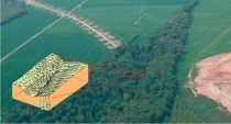
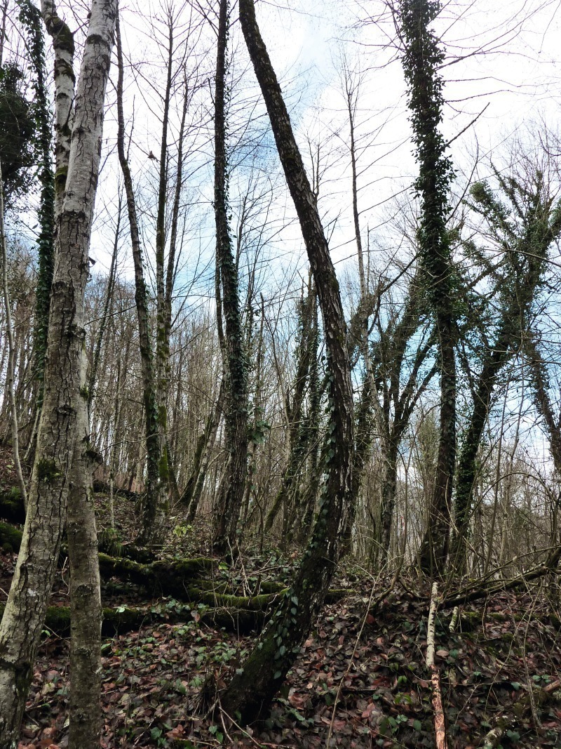
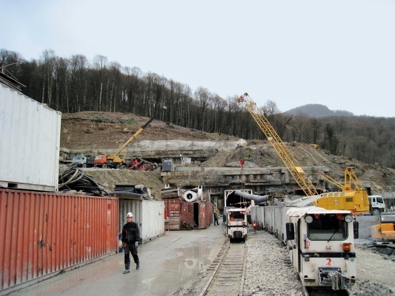
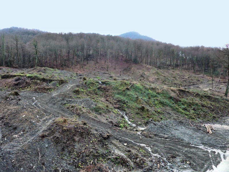
The team joined the project at an already advanced stage, when the routes of the railway and the motorway had already been finalised. Preparatory work on the pilot cuts at the south portal had already started in early 2009. AE identified a potentially unstable slope near the north portal during a visit to the project site. Morphologically, several slip wedges were apparent on this slope. Trees with bowed trunks, and a number of fissures in the terrain, were indicative of movement of the slope (Figure 2). It was necessary, despite the absence of any monitoring, to assume an active slip-endangered slope. The original project planning positioned the portals in the central area of this slope; the risk management therefore assigned a correspondingly high risk rating to this situation. In addition, damage to the tunnel system would have had direct implications for the completion of one of the main infrastructural features for the 2014 Winter Olympics. The magnitude of this risk was explained to the client in the context of risk management. This critical situation led to the client creating the task force mentioned in Section 3 above. More extensive geological and hydrogeological surveys were performed on and around this slope, in order to permit the making of a detailed site-ground model. Exploratory bore holes disclosed a complex system of diverse slip planes and multiple groundwater tables. The unstable slope has an estimated volume of some 5 million m3 and consists of large boulders embedded in a matrix of marl and clay.
The designers were instructed to revise their planning, taking account of these discoveries. In early 2010, they submitted a concept which included stabilisation of this slope. Several rows of slurry walls, to be anchored in the stable substrate, were planned for stabilisation of slope movements around the portals. A drainage tunnel below the slope, and a number of wells, which were intended to relieve the slope of destabilising flow forces, were planned for drainage of this slope.
This concept was examined and evaluated by the task force. The effectiveness of the drainage concept was found to be questionable, due to the poor permeability of the densely cohesive slope soil. It also appeared extremely doubtful whether the planned slurry walls would be able to stabilise a slope of around 5 million m3. No geotechnical data which would have permitted more accurate assessment of the situation were available; it was still not known what parts of the slope were moving, and to what depth and at what speed. In view of these circumstances, the risk involved in the concept submitted by the designer, particularly with respect to the operational safety and reliability of this infrastructural system during the games, was classified as “high”. A diversion of the route, avoiding the slip-endangered slope, was proposed by the task force, in order to minimise the risk; the client accepted the opinion of the task force. It was necessary to define the new route and revise the existing planning within only a few weeks, since tunnelling operations had, in some cases, already started at the south portal. This was achieved only thanks to close co-operation between the designer, the contractor and the task force. A number of variants were drafted, analysed and assessed, the main assessment criterion for these variants being completion time, since the project was already well behind schedule.
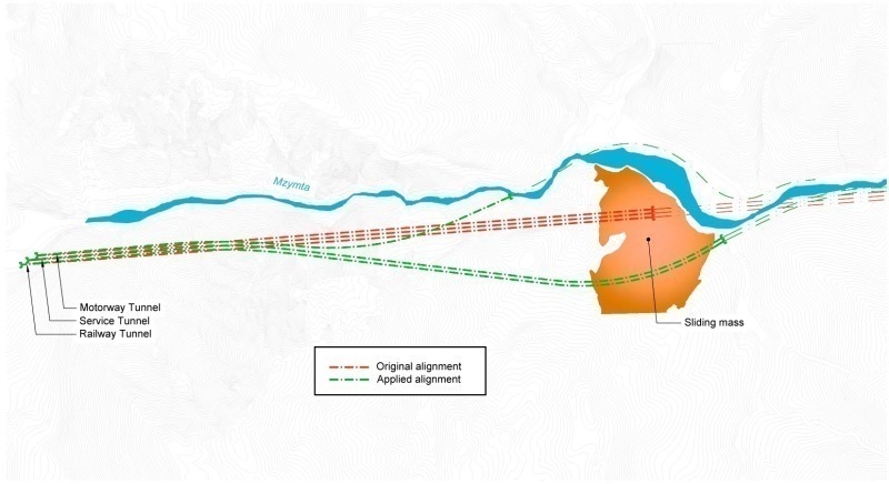
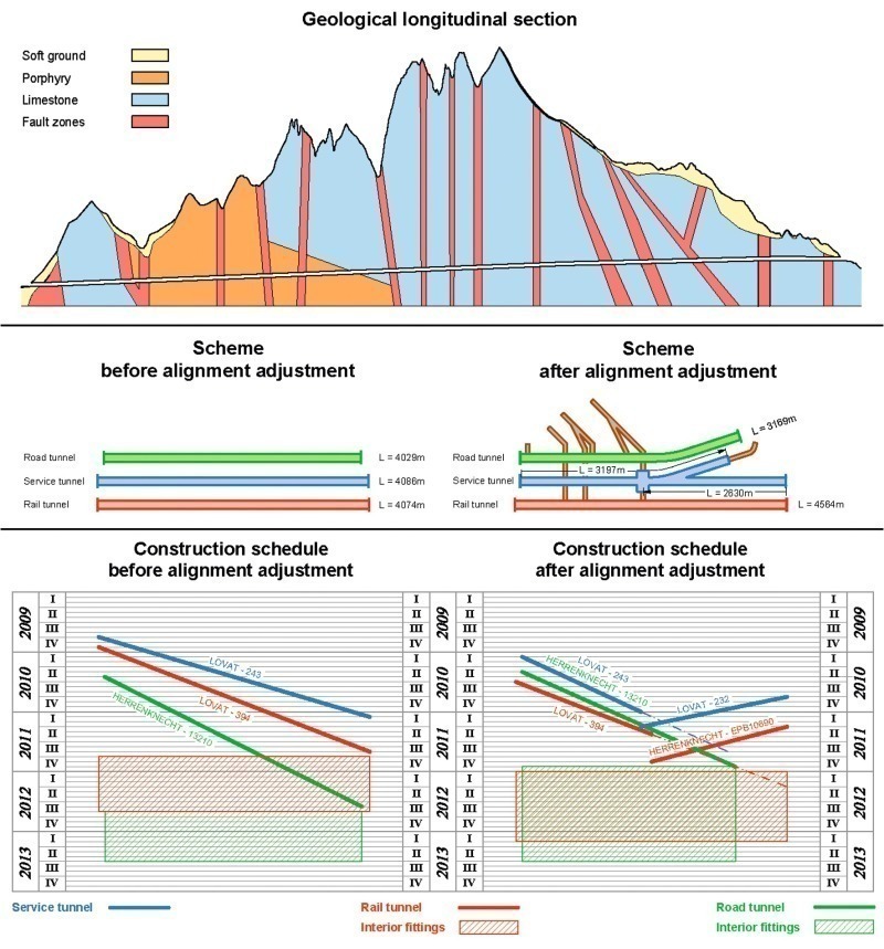
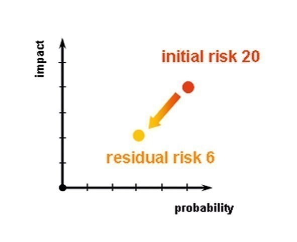
In the variant ultimately implemented, this unstable slope is avoided by the road tunnel on the downhill side, and by the service and rail tunnels on the uphill side (Figure 3). The road tunnel will be 860 m shorter, and the rail tunnel 490 m longer, than originally planned, as a result. The re-planned portal of the motorway tunnel is located in an inaccessible valley at the centre of a vertical rock face and can therefore be accessed only by means of an inclined rope bridge. The revised portal of the rail tunnel, including the service tunnel, emerges from the rock slightly to the north of the unstable slope. The action taken reduced the original risk significantly (Figure 4).
4.2 Tunnelling methods
4.2.1 Conventional tunnelling
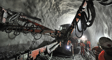
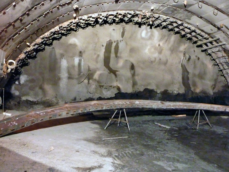
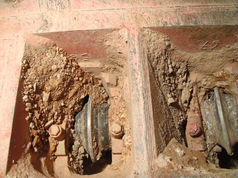
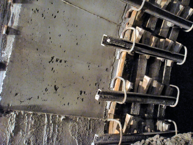
In the conventional Russian tunnelling method, excavation is performed using road-headers, excavators or by means of blasting, depending on rock strength, road-headers being preferred wherever possible. After excavation, an I-beam is positioned, and the space between the last arch and that newly positioned is shuttered by means of wooden boards or formwork panels. The formwork panels are braced by means of wedging against steel or wooden sections, which are inserted into the mountings welded to the tunnel arches (Figure 5). The cavity between the arches is filled with in-situ concrete via concreting windows. Re-injection is also possible via an opening in the roof, if necessary. Only one type of rock-fall protection, which is not modified on site, is generally provided on this project for all geological and geotechnical sectors.
The rock-fall protection installed achieves a relatively high support resistance. This procedure offers very little flexibility for optimisation of the rock-fall protection systems to meet the changing conditions encountered, however. Installation of this manual type is, in addition, extremely time-consuming.
The procedure for selection of rock-fall protection systems for conventional tunnelling customary in Switzerland, inter alia, was recommended to the client and the contractor in order to accelerate tunnelling and make good the delays vis-à-vis the completion schedule. Here, a number of rock-fall protection variants are proposed for the various hazard combinations. These are then installed on site to match the conditions actually encountered. Conversion of the rock-fall protection systems to shotcrete, reinforcement mesh and rock-bolts achieved a further acceleration. It is also not possible without further consideration to modify on site the method envisaged in the project for excavation of the rock. It would be necessary to modify the project, and obtain approval, to permit a change in the tunnelling method used, from boom-type roadway headers, for example, to drilling and blasting in hard compact rock. It is therefore extremely difficult at site level to optimise – and thus accelerate – tunnelling in good geological conditions. Despite massive protests on the part of AE, there continues to be no verification of system performance by means of geotechnical measurements.
It ultimately proved possible in sectors with compact solid rock, at the north portal of the motorway tunnel, for example, to implement a rationalised support system consisting of various combinations of shotcrete, rock bolts, reinforcement mesh and truss beams.
4.2.2 Mechanised tunnelling
Five TBMs are deployed for Tunnel Complex 3 and are summarised in Table 2.
AE drafted various concepts for minimisation of risk. The examples below provide an overview of the studies prepared.
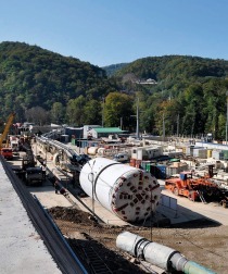
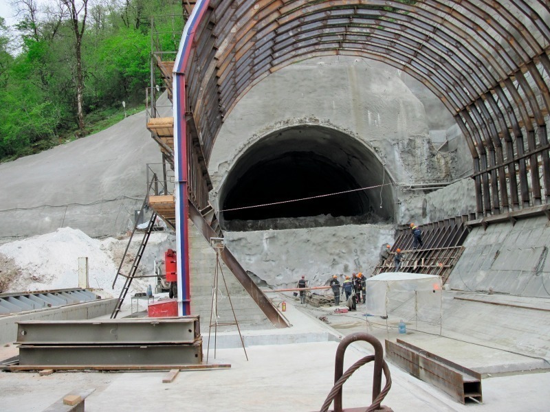
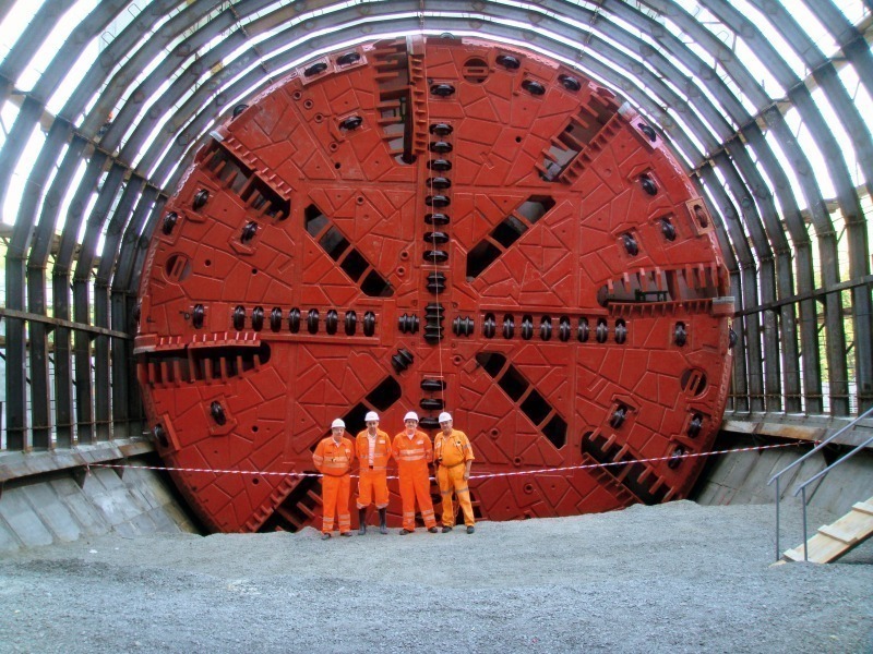
The TBMs and their configurations had been selected prior to the start of the assignment. It was necessary, within the tight time window, to make decisions concerning selection of the TBMs, despite the fact that the geological conditions were not adequately known. The pilot cut was created by means of jet-grouting and drilled piles before the Herrenknecht TBM (13,26 m cutter head diameter) started tunnelling from the south portal of the motorway tunnel. There was an elevated risk of collapse if TBM tunnelling had been started immediately, since the portal is located in the scree. In order to minimise risk, corresponding provisions were elaborated and conventional tunnelling under the protection of a pipe arch until solid rock could be reached was recommended. For completion-time reasons, only the roof zone was driven, and the bench then excavated using the TBM (Figure 6). This entailed the risk that the cutter head (weight 1.400 t including internals) might “dip” during driving of the bench in the scree material. More detailed investigations indicated that the risk of dipping was extremely slight, given adherence to certain control conditions for the TBM. This proved to be correct, and the TBM was able to excavate the bench successfully and continue on to normal tunnelling.
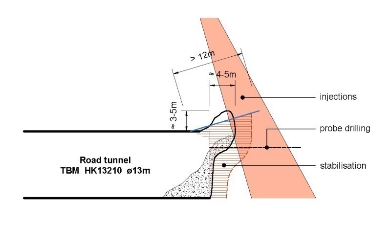
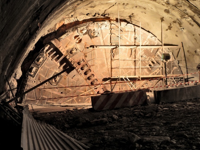
Immediately upon departure from the final pipe arch length, the face lost stability, and collapsed back to the pipe arch. A 3.5 m high collapse occurred above the TBM, trapping the cutter head, which had to be freed manually. The resultant cavity was filled with foam and stabilised. The situation was investigated, and it was concluded that it would be necessary to assume an unstable face and further collapses until the geological conditions improved. Various tunnelling aids possible from the TBM and from the surface, and intended to contribute to stabilisation of the face, were examined. Grouted pipe arches of a length of 12 m were installed length-by-length from the TBM, and face injection-grouting using foam and cement performed to lengths of 4 to 5 m. In addition, jet-grouting campaigns were implemented from the surface both above and in front of the cutter head (Figure 7).
It proved not to be possible, despite these provisions, to stabilise the face adequately. Exploratory bore holes from the TBM indicated that the fissured zone continued further to the north. For this reason, counter-tunnelling was performed from a side access tunnel in the fissured zone explored, in order to free and protect the cutter head in the roof zone (Figure 8). More powerful motors were also fitted to the TBM, and a portion of the openings in the cutter head closed. Since tunnelling operations here were well behind schedule, the roof zone was conventionally driven from side access adits in the forecast faulted zones, in order to assure the completion date. These adits were approached by means of a road specially laid in this inaccessible terrain.
4.3 The construction schedule
Tunnel Complex T3, due to its length of around 4 km (in the original variant) and the geological imponderables, was from the inception the most time-critical complex. The unstable slope at the north portal, and the new planning thus necessary, additionally exacerbated the problem. The new routing lengthened the railway tunnel to some 4.5 km, shortening the road tunnel to approx. 3.2 km.
Under the original planning, excavation of the rail tunnel was to be completed in the third quarter of 2011, that of the motorway tunnel in the third quarter of 2012. The new routing put these dates back to late December, 2011 for the motorway tunnel, and late March, 2012 for the rail tunnel (Figure 9). Scheduled completion of tunnelling in March, 2012 constitutes a great risk of delayed completion of the tunnel, and thus of the entire rail line. In addition to various risk-reducing provisions, such as the creation of access tunnels for geological surveying in sectors where fault zones are suspected, and injection-grouting from the previously completed service tunnel in fault zones, this risk can, above all, be reduced by means of counter-tunnelling. The TBM previously used in Tunnel Complex 5 is to work from the north portal; the 2 TBMs will meet in the tunnel, and must be dismantled there. This is to be accomplished by “gutting” the TBMs, in order to eliminate the necessity for a large dismantling cavern. The target is completion of tunnelling in 2011, in order to leave sufficient time for installation of rail equipment and for trial operation.
5 Summary
A large number of demanding geotechnical and tunnel-engineering challenges need to be overcome in construction of the various tunnel projects on the route from the Olympic Village on the Black Sea coast to the winter-sports region in the Caucasus mountains. Many of these problems are the result of lack of information concerning the geological and geotechnical conditions. A critical factor in this project is the extremely short planning and construction period, combined with the absolutely fixed completion date. It is therefore no surprise that planning has, in some cases, been inadequate, and that a relatively high level of risk has frequently been accepted. It must, however, be noted that appropriate provisions for risk minimisation have been implemented in the case of those risks which endanger on-time completion.
Despite the fact that certain problems must still be anticipated, it is confident that the new transport links will be completed on time, and that the 2014 Winter Olympics will be a resounding success.