Kaiser Wilhelm Tunnel: Undertunnelling
Uptown Cochem in EPB Mode
The breakthrough of the mechanised drive for the New Kaiser Wilhelm Tunnel represented an important step towards applying the safety level required nowadays for railway tunnels. The excavation was carried out in open and closed mode. This report deals with the most difficult technical part-section in terms of tunnelling, which resulted in uptown Cochem being undertunnelled in EPB mode. The technical challenge was geared to undercutting old, in some cases already damaged structures with minimal settlements. The geological conditions (mixed face conditions) and short distances between foundations made it even harder.
1 Stage reached in accomplishing the Kaiser Wilhelm Tunnel
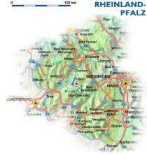
The 2-track Kaiser Wilhelm Tunnel, which opened back in 1879, is located on the Coblenz-Perl Moselle rail route between Ediger-Eller and Cochem, which is an important component of the Trans-European Network (TEN for conventional traffic.
On account of the structural state and the insufficient safety level regarding fire and catastrophe protection it was essential to build a second tunnel apart from renovating the old one.
[<cTracking:-10>] The total redevelopment of the tunnel is divided into 2 phases. In the first construction phase the Old Kaiser Wilhelm Tunnel (AKWT) is augmented by a second bore running parallel, the New Kaiser Wilhelm Tunnel (NKWT), provided with a single track, which is then put into service. In the second construction phase the AKWT is decommissioned and also modified and redeveloped as a single-track tunnel.
Both bores will ultimately be operated with single tracks and connected with each other by means of 8 cross-passages. In this way the tunnel will comply with the latest safety standards in keeping with the guideline issued by the Federal Railways Office (EBA) “Fire and Catastrophe Protection Requirements for Building and Operating Railway Tunnels” and also the European regulations of the TSI – SRT (Technical Specification for Interoperability – Safety in Railway Tunnels). It is planned to open the completed project in December 2015.
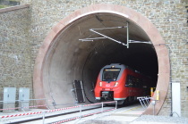
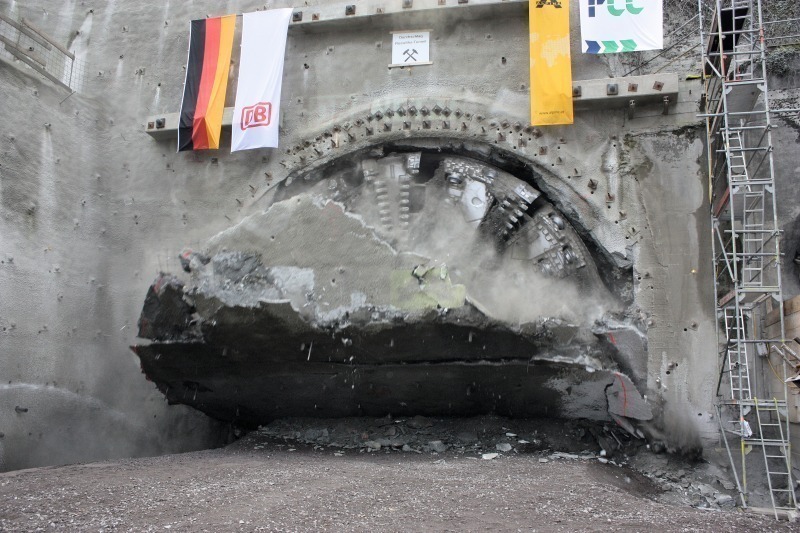
The mechanised drive for producing the 4,242 m long New Kaiser Wilhelm Tunnel (1st construction phase) was successfully concluded with the breakthrough on November 7, 2011 (Fig. 1).
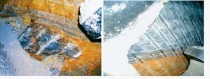
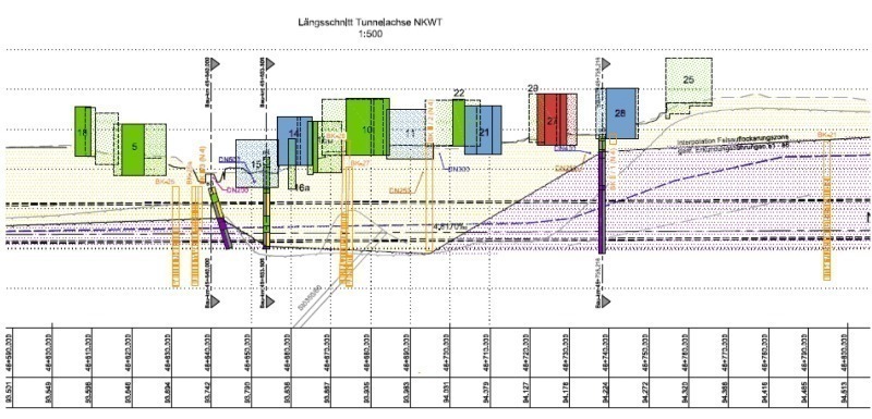
The technically most difficult part-section of the mechanised drive in tunnelling terms entailed undertunnelling uptown Cochem in EPB mode (Fig. 2). In the process buildings at a minimum distance of 3.2 m from the tunnel roof had to be undercut to produce minimal settlements. This was the first time anywhere in the world that this driving method was applied for undertunnelling a built-up area with such slight overburden. This was made all the more difficult by the fact that mixed face conditions existed in this area: on the one hand the prevailing rock face and on the other soft ground. The structural state of the affected houses based on the damage recordings taken during the preservation of evidence was by and large assessed as critical for undertunnelling.
The shield machine was devised to cope with the relatively stable solid rock zones encountered along the bulk of the route, which were to be tackled in open mode. However at the same time it was possible in engineering terms to apply an active face support to overcome fault zones and the soft ground zone in uptown Cochem. As a result the machine was equipped with a screw conveyor, which at any time depending on the geotechnical demands could be converted from open mode to pressurised closed mode and vice versa.
The advantages relating to the method and the logistics called for an EPB shield machine type (SMV 5 according to DAUB classification) as opposed to a shield machine with fluid-supported face.
As reported in [1] conversion from one operating mode to the other was accomplished in a short time without major modifications.
General project descriptions on the tunnel, the subsoil, presentations of the mechanical engineering and the findings obtained during excavating in the solid rock sections as well as the transition areas when moving from the stable solid rock zones to instable, highly fissured rock sections, can be derived in the article under [1].
This report deals exclusively with the findings obtained during the preparation and execution stages while undercutting uptown Cochem.
2 Forecast Subsoil Conditions under Uptown Cochem
The roughly 450 m long area undercutting uptown Cochem is marked by soft ground layers consisting of quaternary slope loam or slope debris with varying thicknesses. These soils are highly susceptible to settlement and adopt flow characteristics when affected by water. The layers are embedded in an extensive depression, which is enclosed by sections of solid rock (Fig. 2).
According to prognosis specifications the drive under uptown Cochem was intended to dip from the solid rock into the soft ground layers, until the cross-section was completely enveloped by the soft ground layers. The mixed-face conditions placed increased demands on controlling the shield machine, safeguarding face stability and conditioning on account of the contrary rock properties.
The solid rock properties are characterised by relatively stable conditions in the transition zone, which gradually change to a shattered rock zone. Fissure systems and thick beds as well as accumulations of clay or silt on bedding planes lead to slickenside surfaces, which favour the formation of detached blocks during the drive.
3 Planned Driving Concept to undercut Uptown Cochem
The drive beneath uptown Cochem was to be executed in the closed mode to secure face stability and in turn to accomplish an excavation with as little settlement as possible. Towards this end the machine was designed with further elements minimising the amount of settlement:
• largely closed cutting wheel
• Cutting wheel displacement with the possibility of retracting the cutting wheel
• Revolving rim (rim cutting wheel).
• Integration of mass balance systems for extraction (belt weigher) and annular gap grouting
• Limiting the conicity and the overcut
• Functioning controls for the essential machine components, backed up by optical and acoustic alarm signals so that possible faults are remedied as quickly as possible
• Data processing unit to monitor all data from the machine drive with online data transmission
• continuous monitoring of buildings with online transmission and predetermined alarm, warning and limit values.
In mechanical engineering terms partial supporting of the roof zone by means of a grout curtain from the machine was also planned should the need arise. This furthermore made it possible to undertake supporting directly beneath buildings as precautions close to the surface were difficult to execute on account of the location of the buildings and their accessibility.
4 Execution Concept
A multi-stage programme for working out the execution concept was drawn up chronologically well in advance of undertunnelling uptown Cochem on the basis of the available subsoil information and the driving concept planned in accordance with the details contained in the tender. The execution concept was aimed at establishing a controlled cycle and a safe as well as continuous drive for undertunnelling uptown Cochem.
The programme’s main elements were:
• Assessment of the available subsoil information if need be with further reaching exploratory measures being defined
• Analysis of settlement compatibility of the buildings affected by the excavation
• Definition of engineering and process technical precautions to provide for undertunnelling free of disturbances
• Definition of precautions in conjunction with execution and construction techniques for monitoring the driving activities
• Introducing a measurement concept on the surface through permanent observation of the individual buildings and real time transmission to the TBM control panel
• Advance tests for conditionability and reducing clogging problems
• Investigating the application of in situ tests with regard to injecting the surrounding subsoil
• Additional examination of the building geometries of the critical buildings.
4.1 Assessment of the Subsoil Information
Analysis of the available subsoil information documented that the location of the rock horizon had to be precisely established using additional exploratory drilling. The main intention here was to arrive at a comprehensive as possible assessment of the course of the rock horizon and the related thickness in the excavated cross-section. The accompanying subsoil investigation that had to be carried out should furthermore correct the forecast determining subsoil parameters (ф, c, E-module, grain-size distribution curves, porosity) and the stratification and the cross-sectional structure in keeping with the parameters at the tendering stage.
The 6 exploratory drill holes that were additionally produced indicated that mixed face conditions prevailed in the tunnel cross-section over approx. 230 m ranging from solid rock (clay slate, quartzitic fine sandstone) and soft ground (slope loam, silt, slope debris). The tunnel cross-section was completely located in solid rock in the remaining area that had to be undertunnelled (Fig. 2).
As far as the grain composition was concerned in accordance with the prognosis, the slope loam emerged to be sandy silt containing stones whereas in the case of the slope debris, the silt merely filled the intervening and porous areas between the stony and gravelly grain fractions. Given a silt proportion of ≥ 10 % these soils are highly susceptible to movements and quickly moisten, e.g. when driven over several times. As from a silt proportion of ≥ 20 % the soil is in addition susceptible to flowing in the event of groundwater or ingressing strata water.
Based on these recognitions the settlement compatibility of the critical buildings with shallow overburden was assessed. As a result it was established that additional measures were needed to undercut the most endangered buildings in a safe manner. Altogether around 70 m of the 450 m long undertunnelling section in uptown Cochem was affected.
Test grouting to improve the soil did reveal that the silt-dominated layers were difficult to inject as had been forecast but however the subsoil was able to accept a large amount of grouting material on account of its heterogeneity and pore volume.
4.2 Improving the Soil
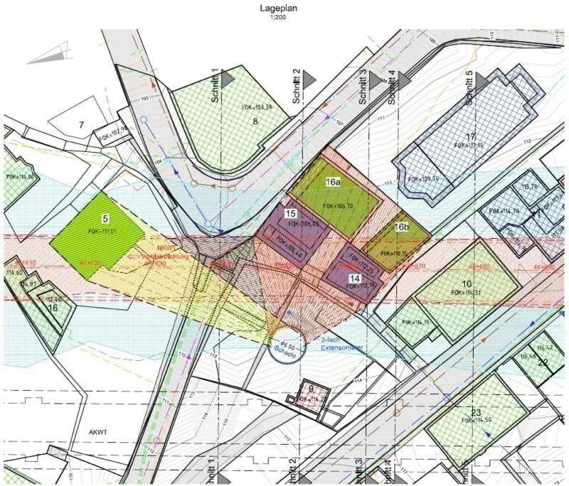
Based on an extensive risk evaluation of possible additional measures to enhance the safety of the buildings and in turn minimise subsoil deformations resulting from the excavation, it was decided to improve the subsoil over a length of roughly 70 m in advance of the drive by means of a grout curtain. The grout curtain acting as a brake on settlement was produced from the surface in a specially created shaft structure and set up more or less centrally between the lower edge of the foundations and the tunnel roof. The shaft was positioned between the Old Kaiser Wilhelm Tunnel and the New Kaiser Wilhelm Tunnel (Fig. 3). The minimum distance between the roof and the lower edge of the buildings amounted to approx. 3 m.
The shaft was produced using reinforced shotcrete and a strengthening ring at the shaft head. The shaft had a clear diameter of 6 m and a depth of 12.8 m. Any build-up of water pressure was prevented by setting up relief drill holes.
An excavation without any advance supporting was precluded along this section on account of the risks for the buildings. Direct underpinning of the buildings, e.g. using a pipe umbrella support from special shafts with the buildings being secured by supporting jacks was disregarded as unsuitable even during the production stage owing to the large number of points of attack, restrutting and deformations.
A 2 to 3 mm amount of lift was defined as the goal for safe undercutting. Depending on the resultant settlement trough it also had to be possible to compensate settlement through homogenisation.
The Soilfrac method from the Keller Grundbau GmbH was applied. The parameters regarding the degrees of lift formulated from the static point of view were safety attained.
No additional measures were undertaken for the remaining section to be tackled.
4.3 Engineering and Process Technical Precautions for Undertunnelling
The basic approach for safely undertunnelling uptown Cochem was to accomplish a continuous drive, i.e. continuous operation day and night without any scheduled break in tunnelling. As a consequence the following preventive measures were adopted at a sufficient gap prior to the undertunnelling measure as such:
• Servicing and inspecting the complete driving installation, particularly the cutting wheel, screw conveyor, foam lances for adding additives and calibrating the belt weigher. The result was recorded in a special report. Deficits and flaws were remedied on the spot.
• Installation of additional cutters to cope with the slope debris and slope loam layers
• Replacement of the grill bars
• Replacement of the cutting rollers by special cutter rollers with double seal, high-grade steel and filled with lubricant to prevent blockage
• Testing the compressed air lock to check how it is functioning.
Extensive test series relating to conditioning (pastosity) and to reduce clogging phenomena were carried out in advance for adapting the earth paste optimally as well as its properties vis-à-vis the subsoil. Furthermore 2 test sections were defined under driving conditions, which served transference to the subsoil and evaluation during the drive in addition to the lab tests. Geotechnically unfavourable conditions existed for the EPB mode itself, which were characterised by the mixed face conditions and the simultaneous occurrence of sectors of soft ground and solid rock.
The tests revealed that the conditioning agent Rheosoil 143 from the BASF AG (anti-clay adhesive) was able to safety fulfil the required demands.
The ground was plasticised to a sufficient extent so that the extraction chamber could be completely filled and pressure maintained. This requirement was proved both in solid rock as well as soft ground. At trhe same time adhesion and cohesion were sufficiently reduced. To monitor the temperature development in the earth paste, 2 temperature sensors were additionally installed in the extraction chamber. Openings for ventilating the roof were installed to provide for foam injections or the accumulation of foam in the roof zone, so that clearly defined supporting pressure conditions were also attained in the roof zone.
The fine adjustment of water, bentonite and foam additive and the effective addition of compressed air were geared to the power input for the cutterhead drive. Values of 60 to 80 % emerged to be favourable in prior tests.
4.4 Precautions during Execution and Construction Operation
For interpreting the preservation of evidence for the buildings a subsoil and building monitoring programme (water level gauges, plug gauges) with the corresponding warning, alarm and limit values, was defined. In addition the deformation behaviour of the segmental lining including any changes to the joint packing and joint gap dimensions was monitored. The measurement data were recorded and transmitted by automatic means. Furthermore the shield operator was informed continuously about the measurement results in evaluated form via a separate monitor. For the shield operator the flood of data was reduced to the bare bones by means of integrated alarm annunciators.
The valid parameters relating to the drive with regard to the support pressure and the machine parameters (e.g. contact pressure force, torque and rpm of cutting wheel, rate of advance, cutting wheel displacement, overcut, mass balance, power intake for drive, driving jack pressure, mortar grouting pressure, settings for foam unit) were passed on directly to the shield operator by the site management in the form of special instructions. The entire driving screw was correspondingly attuned for a safe tunnelling procedure thanks to a number of training sessions and briefings.
Sufficient equipment and materials (drilling tools, conditioning agents) were kept available for possible additional measures (pipe umbrella, grouting material, shotcrete, silicate foam) at fallback level.
Local residents were familiarised with the technical implementation and realisation process by means of a number of information evenings and in personal discussions. All in all the response was positive.
Should partial settlements with face inspections become necessary in spite of all the precautions, the subsoil had to be sufficiently impregnated with bentonite during the transition from the earth paste-supported mode to the compressed air-supported one.
Special incident catalogues also regulated the measures that had to be mastered depending on the incident scenario in addition to the preventive measures. Towards this end it was also planned to execute regrouting through the segment tube should the need arise.
A decision-making team was set up for the critical section being undertunnelled. It comprised the project management and the client’s on-site supervision, the JV’s site management and the advisors for the contractors present on the construction site. In addition an alarm plan with the appropriate reporting chain was drawn up. The undertunnelling project took place on the basis on the planning documents and statics scrutinised by the EBA test engineer Dipl.-Ing. Reinhold Maidl and approved by the DB ProjektBau GmbH, especially for the support pressure and annular gap grouting.
5 Findings obtained during Execution
Thanks to optimal adjustment of the support pressures, by and large controlled via the admission of the pressure of the earth paste and annular gap grouting pressures on the subsoil and the deformation behaviour of the buildings, it was possible to accomplish a continuous frictionless excavation so that settlements were kept far below the forecasts.
Subsequent adjusting and regrouting to compensate settlements from the shaft were confined to a few points with only minimal lifting measures being introduced.
The transitions from rock to soft ground and vice versa were accomplished resulting in low subsoil deformations thanks to the proper and sensitive application of the open and closed operating modes. The machine data were continuously compared with the subsoil deformation behaviour. There was no need for chamber inspections with lowering of the earth paste level. The incident scenarios previously defined on the basis of a comprehensive analysis were mastered safely by means of sensitive monitoring and measures resorted to prior to the excavation. A corresponding catalogue of measures as fallback level was defined in addition to the scheduled measures that were to be resorted to. In the case of the scheduled open mode switching to closed mode was foreseen as the fallback level. Further-reaching fallback levels such as additional subsoil improvements – also undertaken from the machine – were not required.
6 Summary
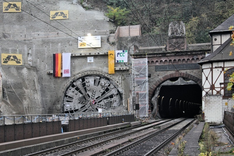
Undertunnelling uptown Cochem altogether posed high demands both on the machine design and the driving crew. The execution concept was agreed on during the course of intensive discussions between the client (and his advisors) and the contractor to ensure optimal adaptation to the subsoil and building properties. The optimal preparation, coordination and partner-like collaboration of all those involved in the project were determining for the successful and technically challenging project to undertunnel uptown Cochem (Fig. 4).
In summing up it can be maintained that undertunnelling uptown Cochem with highly sensitive residential buildings and minimal distances to the foundations of 3 m was executed without any problems regarding the stability of the face and industrial safety using the EPB mode.
Buildings were only affected by slight damage caused by settlements in the form of cracks. The segmental lining was produced in the highest quality without damage and fulfilled the requirements posed on a watertight structure to the very utmost.