Saving Energy and Resources and Reducing the Carbon Footprint by Innovations in Tunnel Construction
Climate protection and the geopolitical situation pose major challenges for our society. To protect the climate, we must reduce CO2 emissions and cut the consumption of fossil energies. The war in Ukraine makes us very aware of our economy‘s dependence on fossil energies and their availability and costs. This makes savings even more urgent than they already have been before. Likewise, the relevance of supply chains and availability of raw materials is becoming more and more obvious – also for the construction industry. An optimization of the design of conventional tunnels by owners and planners can lead to a significant reduction in CO2 emissions, energy and raw material requirements, and thus also in cost. In the article, potential optimizations are shown and explained with the help of examples.
 By optimising the planning, considerable reductions regarding the carbon footprint, energy and raw material requirements can be achieved for conventional tunnelling
Credit/Quelle: WBI

1 Introduction
Climate protection and the geopolitical situation pose major challenges for our society. To protect the climate, we must reduce CO2 emissions and cut the consumption of fossil energies. The war in Ukraine makes us very aware of our economy‘s dependence on fossil energies and their availability and costs. Savings become even more urgent than they already have been before. Likewise, the relevance of supply chains and availability of raw materials is becoming more and more obvious – also for the construction industry.
Recent studies show that transport infrastructure construction also contributes significantly to CO2 emissions as well as to the consumption of energy and raw materials. In this respect, we are all called upon to contribute to improvements in every possible way. This is done in many ways, as e.g. shown in [3] and [5]. As stated very appropriately in [4], an overall view including all relevant aspects is required. This should also be objective and based on facts and not on false figures or be ideologically motivated, as is unfortunately sometimes the case. Therefore, we as civil engineers must actively participate in these discussions and make our contribution.
In [1], on the basis of [2], CO2 emissions totaling 2127.62 kilotons were determined for the construction phase of the Brenner Base Tunnel. More than 80% of these emissions resulted from the demand for cement and steel. Also for two railroad tunnels excavated with a TBM and for two highway tunnels built with the conventional tunneling method, it is shown in [1] that more than 80% of the CO2 emissions in the construction phase are attributable to the construction materials cement and steel. Furthermore, the production of these two construction materials is energy intensive. At the same time, steel is one of the building materials with increasing bottlenecks regarding supply chains and considerable price increases.
Against this background, reducing the need for cement and steel can make a significant contribution to reducing CO2 emissions as well as energy and raw material requirements in infrastructure construction. This comes along with a significant reduction in construction costs, which is in line with the economic efficiency imperative to be followed by public authorities who are in charge of transport infrastructure.
In this article, possibilities for optimizing the design of conventional tunnels are presented that can contribute to a considerable reduction in the demand for the above-mentioned construction materials. The article does not draw up an all-encompassing carbon footprint in connection with the con-struction of traffic tunnels, but rather focuses on these very building materials and their savings through optimised planning. Similarly, we do not claim to be exhaustive in our discussion of optimizations. Rather, our aim is to point out possible optimizations and the corresponding contribution on the part of owners and tunnel planners.
2 Design and Stability Verification
In tunnel construction, the subsoil is an essential load-bearing element. Therefore, it is crucial for an economical and safe design to realistically model the subsoil and the support or lining as well as their mutual interaction.
The authors have presented a rock mechanical and rock hydraulic model for fractured rock masses [6–9], which they have been using successfully for many years in conjunction with WBI‘s own three-dimensional finite element programs FEST 03 and HYD 03 for the design of tunnel structures in rock masses as well as in soil. In almost all executed projects, displacement and stress measurements were carried out and compared with the predictions. In this way, the authors have acquired a high degree of forecasting reliability, which can be used for future optimization of tunnel designs with regard to reducing CO2 emissions, energy consumption and raw material requirements, and thus also costs. This is explained below using selected examples. In this context, we would also like to point out that corresponding calculations based on the authors‘ model can in principle also be carried out with the Sofistik program, so that the procedure is also open to other planning offices.
3 Basic Considerations for Optimizing the Tunnel Cross-Section and Excavation Sequence in Conventional Tunnel Construction
In the first instance, the choice of tunnel cross-section is determined by the requirements resulting from the later use of the structure. For example, there are different requirements for the cross-section design for single or multi-lane road tunnels, for single and multi-track railroad tunnels and for underground stations. Furthermore, the ground and groundwater conditions result in certain requirements for the shape of the cross-section.
Considerations of the stability of the temporary working face and construction-related aspects finally lead to certain sequences of excavation in partial cross-sections. This also means that areas temporarily supported with reinforced shotcrete and anchors have to be excavated again and the corresponding support materials disposed of. Obviously, this is unfavorable regarding carbon footprint, energy and raw material require-ments and costs. This is the case, for example, with sidewall headings and advancing vault excavation with temporary invert. Here, moreover, heavy reinforcement often results at the transitions from the partial cross sections to the final cross section.
Irrespective of the excavation sequence, the design of the tunnel cross-section has a considerable influence on the material requirements. Flat surfaces and corners or insufficient curvatures of the temporary support lead to bending moments and shear forces and thus require large shotcrete thicknesses and heavy reinforcement. Unfortunately, numerous examples of this can be found in construction practice both nationally and internationally. In contrast, a well-rounded shotcrete membrane is mainly stressed by normal forces and does not require static reinforcement (membrane theory). Achieving this should be the goal of a good tunnel design.
Consequently, the design of cross-sections and the choice of construction sequences can have a considerable influence on the consumption of cement and steel, which has a direct impact on carbon footprint, energy and raw material requirements, and thus costs.
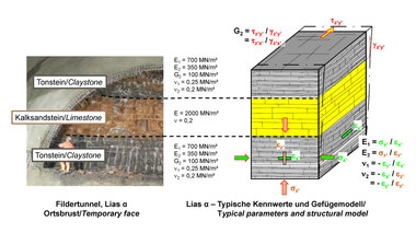
The influence of the construction process will subsequently be explained in more detail by means of a systematic consideration of the cross-section of a two-lane highway tunnel. The rock cover is assumed to 40 m. The rock mass model and parameters are selected on the basis of a project example presented in [6], chapter 3.2 (Fig. 1).
 1 | Study of motorway tunnel in rock mass, finite element mesh, boundary conditions and parameters
Credit/Quelle: WBI
Deviating from the project presented there, the bedding parallel discontinuity planes are inclined at less than 30° in the given case. The stability calculations are performed with the finite element program FEST 03 on a vertical slice section. The 40 cm thick shotcrete memebrane is discretized in the FE mesh by three rows of isoparametric elements (Fig. 2). For comparison, a full face excavation, a sidewall heading and a vault excavation with temporary vault invert were investigated.
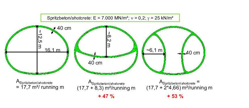 2 | Detail of finite element mesh with investigated tunnel cross-sections and construction sequences
Credit/Quelle: WBI
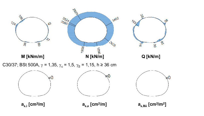
For the vault heading, comparatively large bending moments, shear and normal forces result in the area of the transition to the temporary invert, leading to accordingly large reinforcement against compression and shear (Fig. 3). The stresses in the shotcrete membrane are more favorable for the sidewall heading in the example considered here. However, shear reinforcement is also required in this case (Fig. 4).
 3 | Tunnel heading with advancing vault and temporary vault invert, internal forces and required reinforcement
Credit/Quelle: WBI
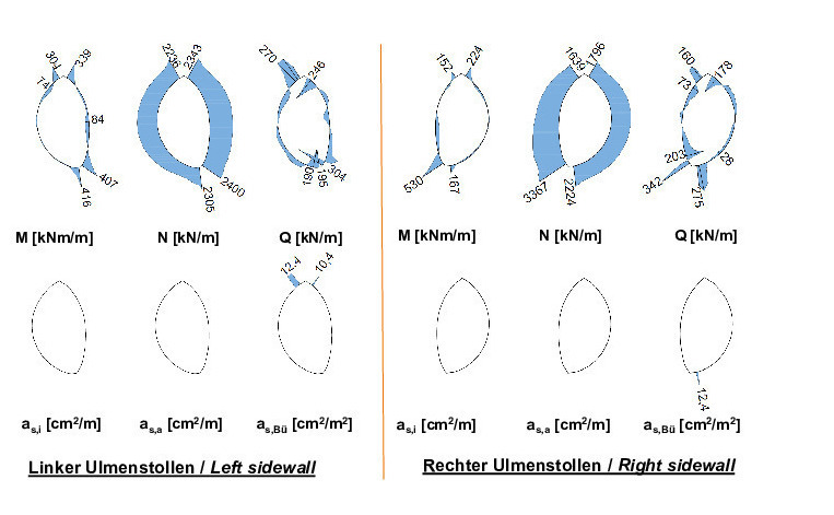 4 | Sidewall heading, internal forces and required reinforcement in right and left sidewall
Credit/Quelle: WBI
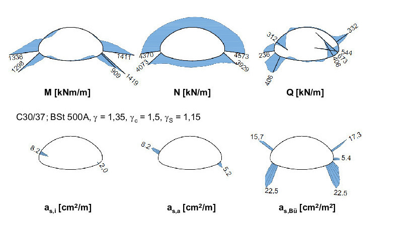
The most favorable loading results from full face excavation. Here, the bending moments and shear forces are small in comparison with the normal forces, so that no reinforcement is required from a structural point of view (Fig. 5). In this regard, it is also possible to dispense with steel arches and anchors. It is advisable to carry out a full excavation with shotcrete support with a certain proportion of steel fibers. Depending on the ground conditions, such a solution may entail greater expenditure for temporary face support, which would have to be taken into account in a comparison.
 5 | Full face excavation, internal forces and required reinforcement
Credit/Quelle: WBI
If only shotcrete is looked at in the given example, and full face excavation is taken as base value, then the additional need of shotcrete amounts to 47% for vault heading, and 53% for sidewall heading (Fig. 2). In view of a shotcrete requirement of 17,7 m3 per running meter of tunnel at full face excavation, these additional quantities are considerable, and their saving leads to substantial
reductions in carbon footprint, energy and raw material requirements, and thus also in costs. Added to this are the aforementioned savings in reinforcement, steel arches and radial anchors, which become possible with full excavation. This leads to a corresponding reduction in steel consumption, which is not quantified here.
For large cross sections, the full face excavation results in large working heights. Since the available construction equipment has only a limited reach, it is currently necessary to backfill the invert and bench areas with excavated material for the vault excavation and to remove this material for the next invert excavation and closure. The energy required for this, is small compared with the savings achieved by shotcrete reduction. Nevertheless, in such cases it is advisable to consider working in two levels, e.g. with suspended monorails. Such considerations must already be taken into account in the invitation to tender for tunnel construction, so that the bidding companies can adequately prepare their construction operations. This is where owners and planners are called upon.
4 Comparison of Sidewall Heading and Full Face Excavation Based on a Project Example
In this chapter, the tunnel headings in two sections of the Stuttgart 21 project are compared with each other. These are the connecting sections on both sides of the new through station.
For the connection of the new through station to the lines leading to Bad Cannstatt and Feuerbach, two dual-track tunnel tubes were driven underneath the mountain Kriegsberg [11]. For the transition of the four tracks from the single-track tunnel tubes from the direction of Feuerbach and Bad Cannstatt into the new eight-track through station, cross-overs and transfer connections are foreseen in the 210 m long section. As a result, comparatively large tunnel cross-sections with widths of up to approx. 22.5 m and heights of up to approx. 16 m were required here.
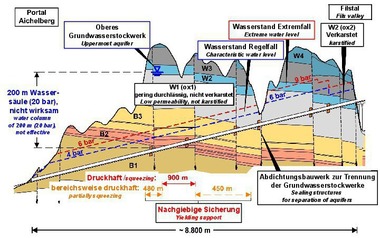
The cover above the tunnel roof amounts to approx. 9 m at the portal wall and increases to approx. 55 m with increasing distance from the excavation pit. The tunnel tubes are located in leached Gypsum Keuper. This is a residual rock mass formed by dissolution and removal (“leaching”) of the sulfates of the competent source rock, the so-called unleached Gypsum Keuper, and by weathering over geological periods.
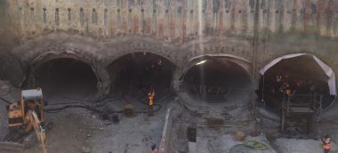
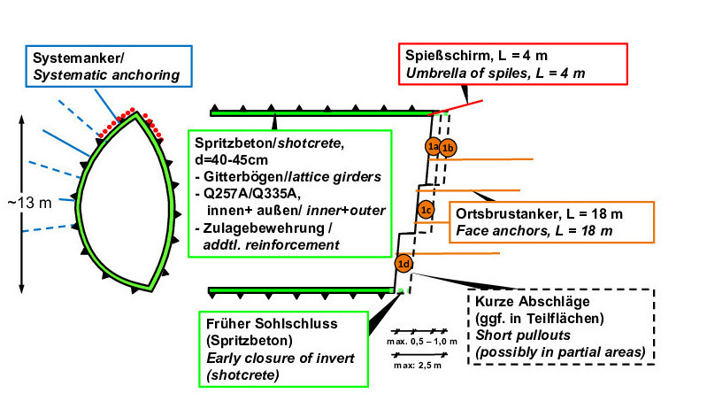
The tunnel sections with the large cross-sections were excavated conventionally with sidewall heading (Figs. 6–8). The sidewall galleries were excavated at full face with a double-stepped face. The round length ranged from 50 cm to 1 m. The invert was closed at the latest 2,5 m behind the face of the sidewall vault. Spiles were installed as roof support and face anchors were installed as face support. A systematic radial anchoring was foreseen (Fig. 6). The core was driven in two steps. In alternation, 10 m of core were excavated and supported, followed by 10 m of bench and invert. The invert was closed at the latest 10 m behind the working face. Depending on the ground conditions encountered and the results of the geotechnical measurements carried out during heading, pipe umbrellas or spile umbrellas were installed at the roof (Fig. 7). The shotcrete membrane is 40–45 cm thick in the outer contour and 35–40 cm thick in the temporary sidewalls. In addition, a temporary vault invert with a thickness of 35 cm was installed in the sidewall galleries in some areas. A 35–40 cm thick temporary invert was also constructed in the core. Two-layer mesh reinforcement was installed, in some cases with heavy reinforcement additions (Figs. 6 + 7).
 6 | Undertunneling of Kriegsberg, sidewall heading, excavation and support
Credit/Quelle: WBI
 7 | Undertunneling of Kriegsberg, excavation and support of core
Credit/Quelle: WBI
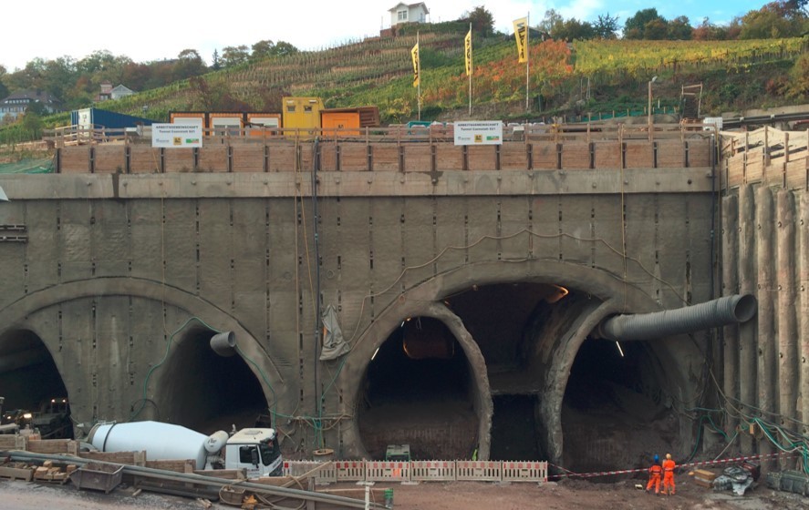 8 | View on portal wall Kriegsberg
Credit/Quelle: WBI
On the other side of the new through station, two dual-track tunnel tubes were excavated to connect the station to the lines leading to the Filder plane and to Ober- and Untertürkheim [10]. This so-called “central station south approach area” is approx. 224 m and 230 m long, respectively. In this widening area, the tunnels have an excavation cross-section of up to 20,0 m wide and 15,6 m high.
The tunnel tubes are located under the dense urban development “Kernerviertel” and have an overburden of approx. 7 m at the main station, which increases to approx. 45 m in the further course of the widening area. Both tunnel tubes are located in the layers of the leached Gypsum Keuper.
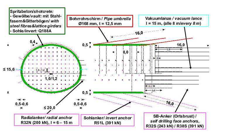
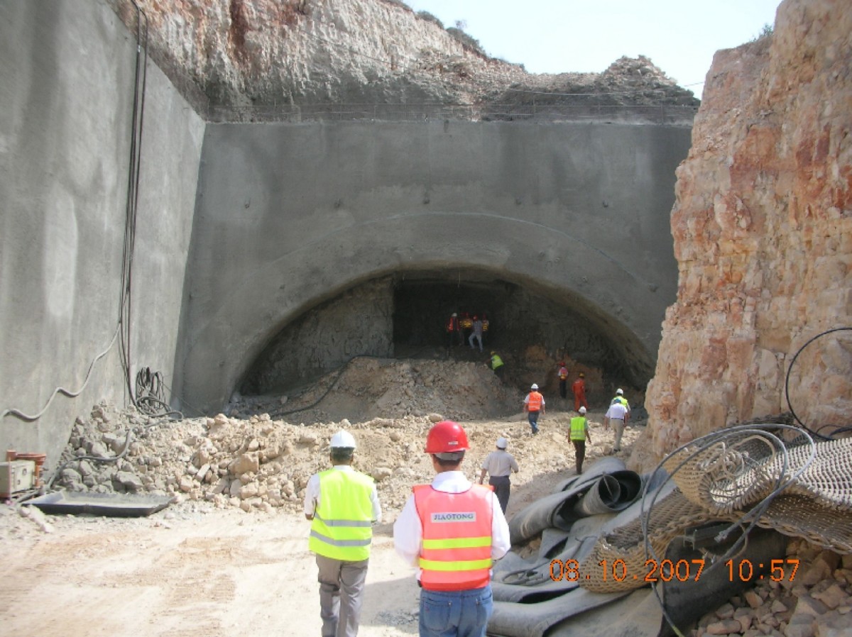
Almost the entire length of the tunnels was excavated in full face excavation with a stepped face (Figs. 9 + 10). The round lengths were 1 m in the vault and 2 m in the bench/invert. The invert was closed after a maximum of 5 m (Fig. 9). Excavation was carried out under the protection of an advance pipe umbrella. The vertical stepped face was supported with 16 m long face anchors. A systematic radial anchoring was installed in the sidewalls and an invert anchoring in the invert area (Fig. 9). The shotcrete membrane is 50 cm thick. Locally, the shotcrete thickness was increased to 60 cm in the sidewalls. In the vault, a steel fibre reinforced shotcrete was installed. In the bench/invert, the reinforcement consists of two-layers of reinforcing steel mats (Fig. 9).
 9 | Heading central station south, full face excavation, excavation and support
Credit/Quelle: WB
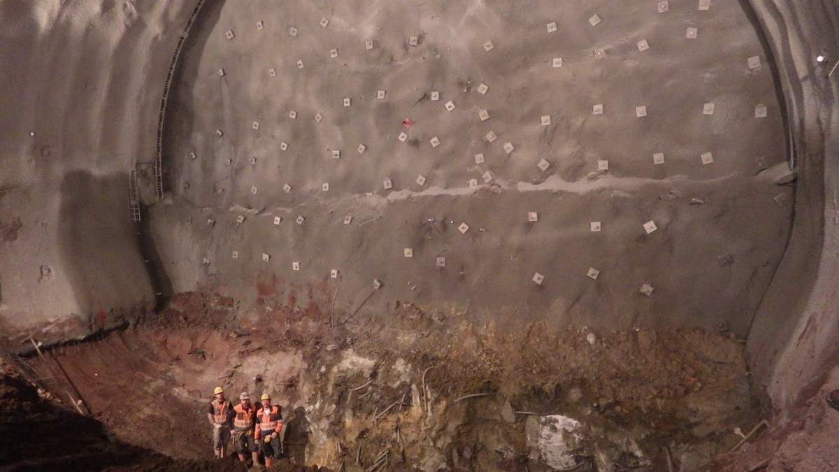 10 | Heading central station south, excavation of invert area
Credit/Quelle: WBI
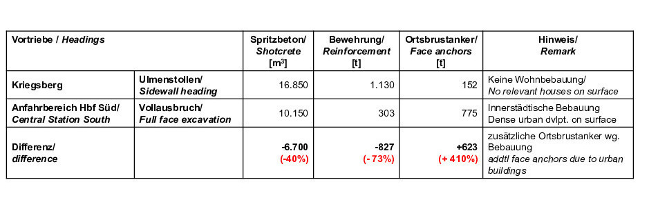
The tunnel headings underneath the “Kriegsberg” and in the “central station south approach area” are comparable with regard to the ground conditions and the excavated cross-sections and lengths. Therefore, the consumption of shotcrete, reinforcement and face anchors is compared in the following. The other support elements are not considered in the comparison, since the driving method (sidewall heading or full face excavation) does not have a significant impact on the number of these.
Significantly less shotcrete was used in the full face excavation in the “central station south approach area”. Due to the elimination of the temporary support of the sidewall galleries, the shotcrete quantities were reduced by 6700 m³. This corresponds to a saving of 40% (Fig. 11). The savings in reinforcement are even more significant. As a result of the reduced shotcrete support and the statically more favorable cross-section in the full face excavation (cf. Chapter 3), 827 tons less reinforcing steel were installed in the “central station south approach area”. This corresponds to a saving of 73% (Fig. 11).
 11 | Headings Kriegsberg and Central Station South, Comparison of shotcrete and steel quantities
Credit/Quelle: WBI
In contrast, significantly more face anchors were installed in the “central station south approach area”. On the one hand, this is due to the larger working face area to be secured. On the other hand, a particularly strong temporary face support had to be installed in this area in order to limit the subsidence when driving underneath the urban buildings. This situation did not exist for the tunnels underneath the “Kriegsberg”, since there were no buildings there. For purely structural reasons, it would also have been possible to install a smaller number of face anchors in the “central station south approach area”, if there would have been no buildings. Under the same conditions with regard to buildings on ground surface, the significantly higher consumption of 623 t (+ 410%) of anchor steel in the “central station south approach area” would therefore be significantly lower (Fig. 11).
Overall, this comparison based on a real project example shows that full face excavation results in large savings in shotcrete and reinforcing steel. To a certain degree this is offset by a higher consumption of face anchors. In total, however, there is a saving in steel, which would have been even higher if the conditions with regard to urban structures at ground surface had been comparable (Fig. 11). It should also be taken into account that demolition, removal and disposal of the temporary support measures (sidewall galleries) are not required for full face excavation. Overall, full face excavation is therefore significantly more favorable in terms of carbon footprint, energy and raw material consumption and costs.
5 Single-Lining Construction
A further, significant reduction in the consumption of concrete and steel for conventional construction of traffic tunnels would be possible if no reinforced concrete inner lining were installed. Corresponding experience is available.
For example, the machine caverns of hydropower plants have been supported with shotcrete only above the level of assembly platforms for turbines, generators and pumps for decades. The roof and walls of the machine cavern of the pumped storage plant Wehr operated by the Schluchseewerke AG in the southern Black Forest, for example, have been stable for about 60 years, and no damage is known. The cavern was excavated in a gneiss similar to the so-called Albtal-granite and supported with reinforced shotcrete and rock nails and locally with prestressed anchors. The groundwater is lowered in the powerhouse area [7, 8].
The Carmel road tunnels in Haifa, Israel, consists of two dual-lane tunnel tubes with 3.2 km length on the western side and 1.6 km length on the Eastern side. The tunnels were excavated by blasting and supported with steel fibre reinforced shotcrete with local additions of structural steel mesh. The tunnels were drained and constructed without a reinforced concrete inner lining. For most of the length, the tunnel floors were constructed horizontally and without support (see, for example, Fig. 12). The bedrock consists mainly of dolomites and limestones with bedding parallel discontinuities [12]. The tunnels have been in operation for more than 10 years.
 12 | Carmel Tunnels, Portal Rupin
Credit/Quelle: WBI
Another example of a tunnel secured only with shotcrete is the escape and rescue tunnel of the Hestenberg Tunnel. The 734 m long Hestenberg Tunnel forms part of the Eastern by-pass of the city of Plettenberg in North Rhine-Westphalia, Germany. It has two lanes and is used by two-way traffic. The escape and rescue tunnel runs parallel to the road tunnel. Both were excavated by conventional means in Devonian sandstones, siltstones and clay shales. The road tunnel is lined with a reinforced concrete inner lining. The rescue tunnel is supported with a 15 cm thick shotcrete membrane reinforced with a structural steel mesh, and it is drained [13].
The above mentioned examples show that, under certain conditions, drained tunnels can be permanently supported with a shotcrete membrane. As already explained, bending moments and shear forces occur only to a minor extent in shotcrete membranes, when the tunnel cross-section is appropriately designed – in particular rounded out. In these cases, no static reinforcement is required. This makes it possible to produce a high quality shotcrete, so that a watertight design also appears possible. Design against water pressure should also be possible without reinforcement.
Against this background, we should work on such solutions in the interest of climate protection and energy and cost savings.
6 Influence of the Ground Model
As already mentioned at the beginning, the ground plays a decisive role in the design of tunnel structures as an essential load-bearing element. Thus, the realistic modeling of the ground is of considerable importance. For the description of rock masses, simplifying classification methods are often used internationally, and unfortunately increasingly also in the German-speaking countries. Frequently, characteristic rock mass parameters are also derived on the basis of the Hoek-Brown model, in which isotropic conditions are assumed. This way, the usually existing anisotropy of the rock mass is neglected. This has already been discussed in detail in [6] and [8], for example. The effects of such ground model on the topics discussed in this article will be shown below using the example of an excavation pit.
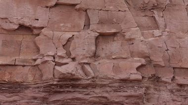
For the stations of the Green Line of the metro in Qatar, numerous excavation pits were built in tertiary limestone. The modeling of the rock mass was explained in detail in [6] and is therefore only presented in very brief form below. For further details, please refer to [6]. The different approaches are exemplarily explained with the aid of a geologic unit called Midra Shale. This is a limestone that shows a pronounced horizontal bedding, with partially small spacing, and steeply dipping joints (photo in Fig. 13).
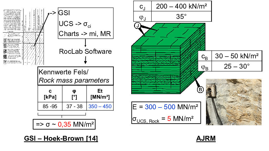 13 | Green Line, Qatar, Midra Shale, Rock mass parameters based on Hoek-Brown [14] in comparison with AJRM [16, 17]
Credit/Quelle: WBI
At that time, the experts initially involved in the construction, determined the characteristic parameters of the rock mass on the basis of the Hoek-Brown failure criterion [14]. The rock mass is considered as a homogeneous, isotropic material. The characteristic parameters determined for the Midra Shale are shown in Figure 13 on the left. Comparatively small isotropic strengths are given, which are in the order of magnitude of the shear strength along the approximately horizontal bedding parallel discontinuities.
At the request of the contractors, the authors carried out their own considerations taking into account the anisotropy of the strength and deformability of the rock mass (Anisotropic Jointed Rock Model AJRM, [6, 8]). Due to the mentioned bedding and fracturing of the Midra Shale, there is an anisotropy in strength, which is taken into account in the ARJM by considering the strength of the intact rock on the one hand and a reduced shear strength along the discontinuities on the other hand
(cf. Fig. 13, right). An isotropic deformability in the elastic range was assumed in the given case.
The deformation modulus is of a similar order of magnitude for both approaches. However, the comparison of the strength characteristics according to AJRM with the strength characteristics obtained with the planner‘s approaches based on Hoek-Brown shows very clear differences. As already mentioned, the planner modelled the rock mass according to Hoek-Brown homogeneously isotropic with strengths in the order of magnitude of the shear strength along the bedding-parallel discontinuities. It was thus modelled more or less like a soil. This does not take account of the actual conditions and, especially in combination with the horizontal bedding, leads to a significant overdimensioning of the support measures.
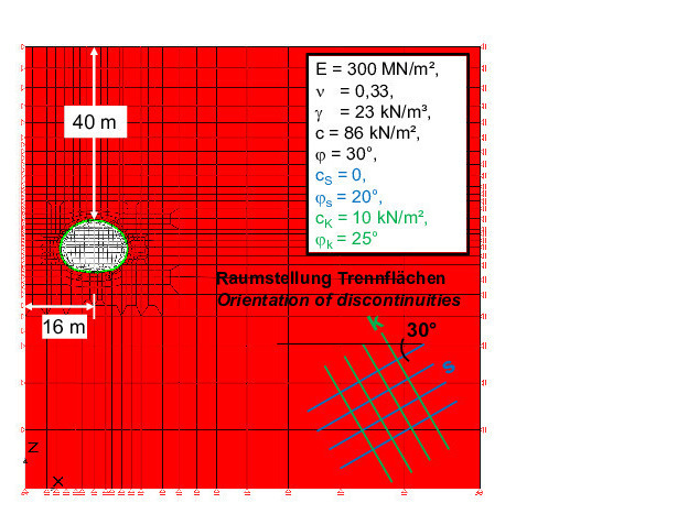
Figure 14 shows a comparison of the excavation pit support, which results from the above outlined ground models, if the same loads are assumed. Modeling the rock mass as a homogeneous, isotropic material with low strength (designer) results in a support with a discontinuous bored pile wall. The bored piles, which had a diameter of 1 m, were tied back every 2.5–4 m with 15–25,5 m long prestressed anchors (see Fig. 14, left). In contrast, the realistic modeling of the rock mass, taking into account the strength anisotropy according to the AJRM, leads to a significantly less extensive excavation pit support with 20 cm shotcrete and up to 8 m long rock nails arranged in a 2 m x 3 m grid (Fig. 14, right).
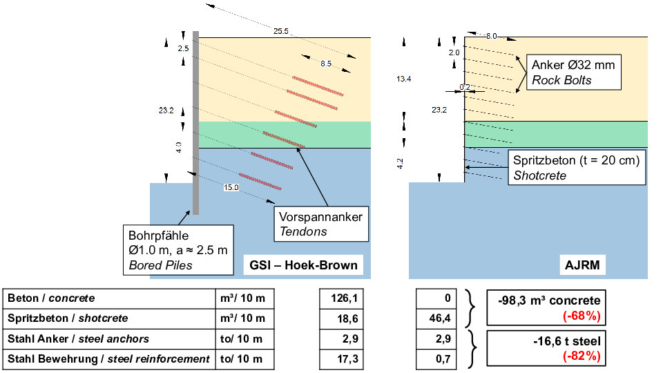 14 | Green Line, Qatar, Support of construction pit dimensioned with parameters based on Hoek-Brown [14] in comparison with AJRM [6, 9] and resulting concrete and steel quantities
Credit/Quelle: WBI
The quantities of concrete, shotcrete, anchor steel and reinforcing steel required in each case for the two differently planned excavation pit supports were determined and compared in Figure 14, below. As expected, the realistic modeling of the rock mass leads to considerable savings: about 68% less concrete and 82% less steel are required to support the excavation pit.
This example makes the importance of realistic ground modeling for carbon footprint, energy and raw material consumption and construction costs very clear. It should be taken as an opportunity to open up to the approaches for realistic modeling of rock masses, which are proven methods for more than 40 years by now [6, 8], and to apply them to an increasing degree.
7 Cut-and-Cover Versus Mining Method
In connection with infrastructure projects, existing infrastructures often have to be undercut. For cost and safety reasons, the undercutting of roads at small overburden is often planned with the cut-and-cover method, combined with correspondingly complicated traffic diversions and obstructions. In some cases, however, mined tunnel solutions have already been implemented (see, for example, [16–19]). This can have advantages also for the topic dealt with in the given article, as demonstrated by a project example.
For the aforementioned Green Line of Qatar Metro, numerous underpasses were planned under heavily trafficked, multi-lane roads using the cut-and-cover method. The authors were allowed to redesign some of these underpasses for application of the mining method on behalf of the contractors [16, 17]. An example of this type is a four-tube structure connecting to the technical building for ventilation and air conditioning of the subway. Originally planned as cut-and-cover construction, after a re-design it was built according to the mining method underneath a busy eight-lane main road at an overburden of about 5 m (Fig. 15). Details on the project and planning can be found in [17].
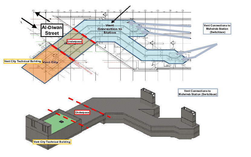 15 | Green Line, Katar, Vent City, schematic plan view and perspective of the structures
Credit/Quelle: WBI
Figure 16 shows a comparison of the tunnel cross-sections designed for the cut-and-cover method and the mining method as well as the corresponding required concrete volumes. Only the change in tunnel cross-section results in a saving of 26% of concrete. In addition, there are considerable savings in steel due to significantly lower reinforcement quantities, which are not quantified in more detail here. Furthermore, the support of the construction pit required for the cut-and-cover method can be completely eliminated, which in turn leads to significant material savings. Also the excavation volumes are significantly reduced when the mining method is applied. Furthermore, the CO2 emissions and indirect costs caused by traffic diversion, traffic obstructions and the resulting congestion are eliminated.
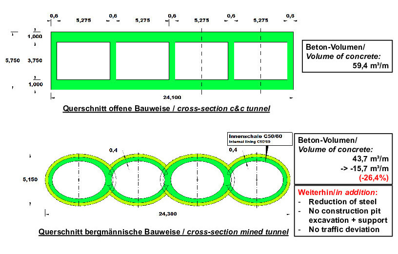 16 | Green Line, Katar, Vent City, comparison of concrete quantities for cut-and-cover and mined tunnels
Credit/Quelle: WBI
This example makes it clear that, in terms of CO2 emissions as well as energy and raw material consumptions, it may well make sense to consider and investigate the mining method as an option for undercutting also at small overburden heights.
8 Summary and Conclusions
Climate protection and the geopolitical situation pose major challenges for our society. To protect the climate, we must reduce CO2 emissions and cut the consumption of fossil energies. The war in Ukraine makes us very aware of our economy‘s dependence on fossil energies and their availability and costs, making savings even more urgent than they already have been before. Likewise, the relevance of supply chains and availability of raw materials is becoming more and more obvious – also for the construction industry.
In tunnel construction, reducing the need for cement and steel already can make a significant contribution to reducing CO2 emissions as well as energy and raw material requirements. This comes along with a significant reduction in construction costs, which is in line with the economic efficiency imperative to be followed by public authorities in charge of transport infrastructure.
In this article, possibilities are presented to achieve such savings in conventional tunnel construction by optimizing the design. These possibilities are explained on the basis of project examples, and the achievable savings are exemplarily quantified.
One option is to optimize the cross-sectional shape of a tunnel in such a way that bending moments and shear forces are avoided. This leads to a considerable reduction in the support requirements. If, in addition, a full face excavation is planned and partial excavations and corresponding temporary support measures are thus avoided, then significant quantities of shotcrete and reinforcement can be saved. In addition, there are savings with regard to demolition, removal and disposal of the temporary support measures.
Furthermore, we should think about constructing single-shell shotcrete membranes as permanent linings. If, through appropriate planning, these are only stressed by normal forces, it is possible to dispense with reinforcement meshes, anchors and steel arches. The shotcrete can then be reinforced with steel fibres, it can be executed with a better quality and – possibly with the aid of additional measures – also watertight.
In terms of reducing CO2 emissions as well as energy and raw material consumption, it may also make sense to investigate undercutting of existing infrastructure at low overburden with the mining method instead of the more common cut-and-cover method.
A realistic modeling of the ground and of the interaction between ground and structure, and the corresponding procedures for stability analyses, play a significant role in economic and safe planning. They are, so to speak, a basic prerequisite. Both the ground models and the calculation methods are available and have been tested over many years.
This article does not claim to be exhaustive. It is rather our aim to point out possible optimizations and thus a possible contribution from owners and tunnel planners – a contribution that we would like to make, and we would like to initiate the discussion in this direction.