Custom formwork
technology for the Jagdberg Tunnel
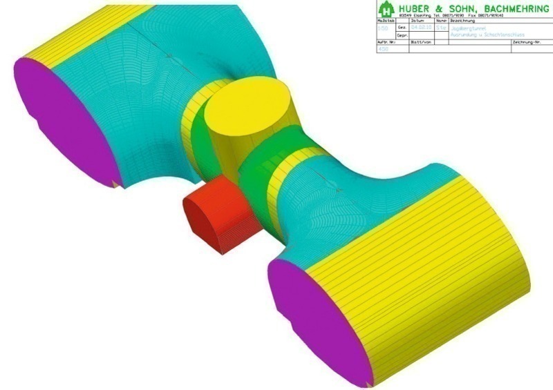 Photo: Huber & Sohn
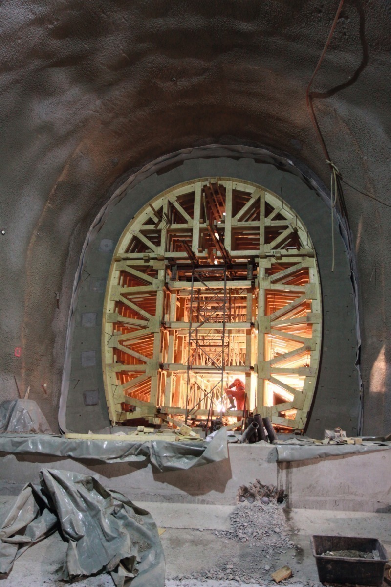 Photo: Knut Johnson
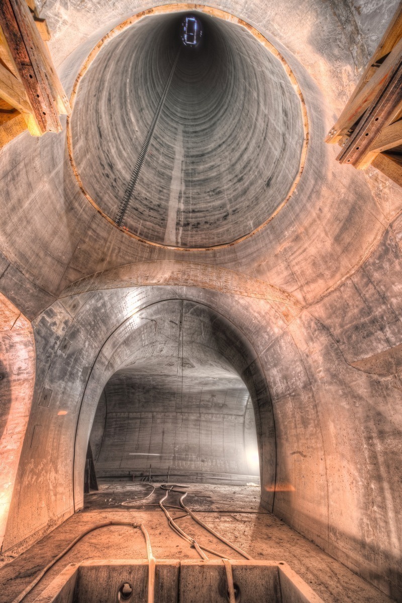 Photo: Wolfgang Sitter, rettis@t-online.de
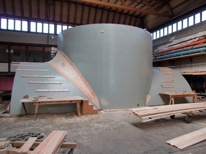 Photo: Huber & Sohn
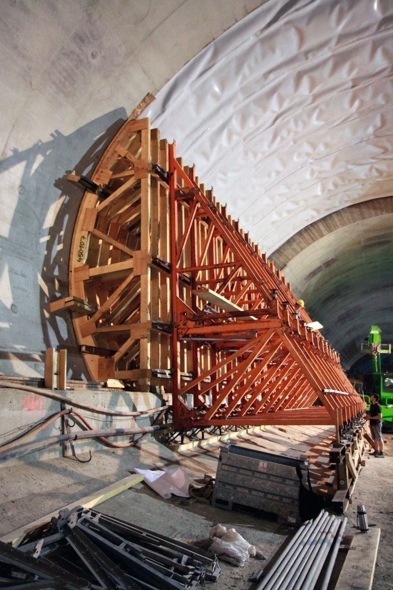 Photo: Knut Johnson
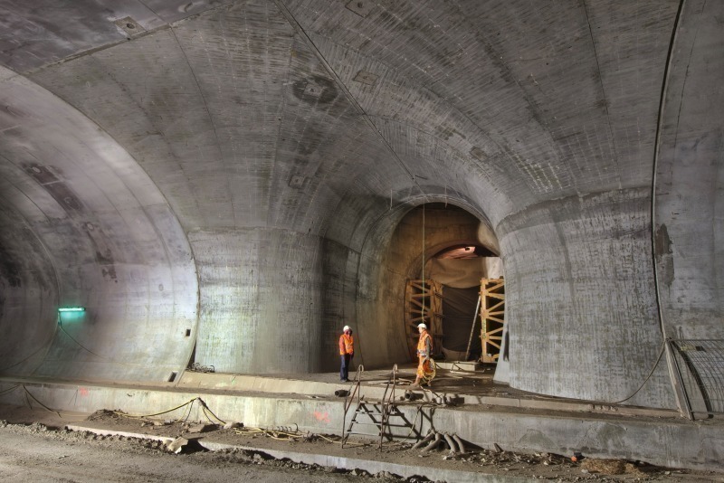 Photo: Wolfgang Sitter, rettis@t-online.de
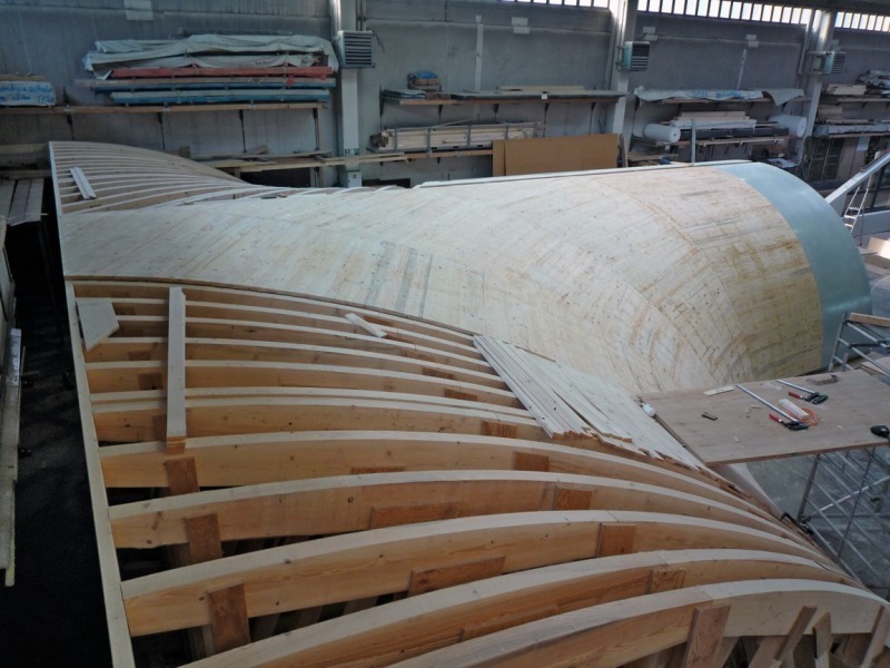 Photo: Huber & Sohn
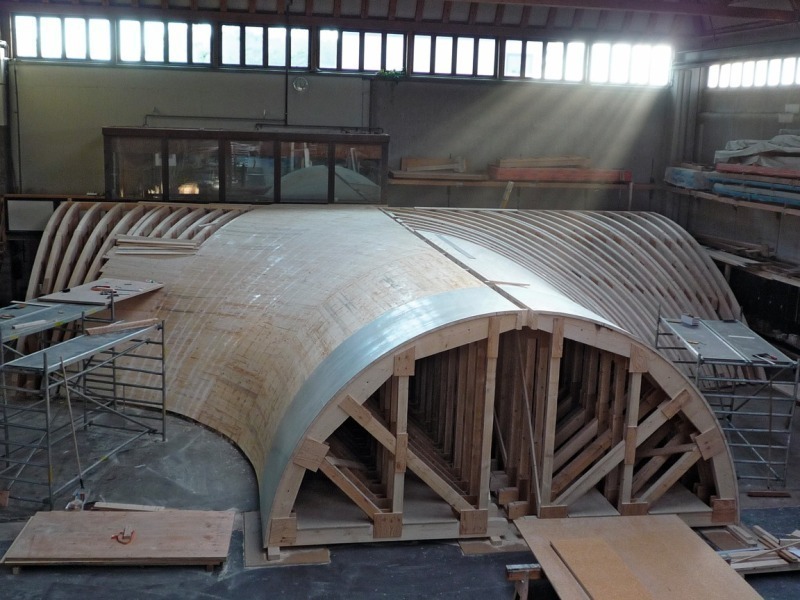 Photo: Huber & Sohn
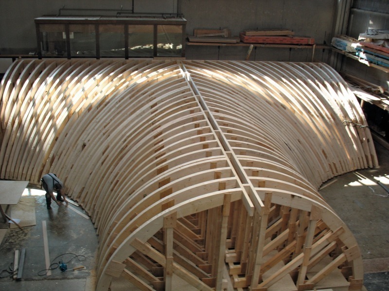 Photo: Huber & Sohn
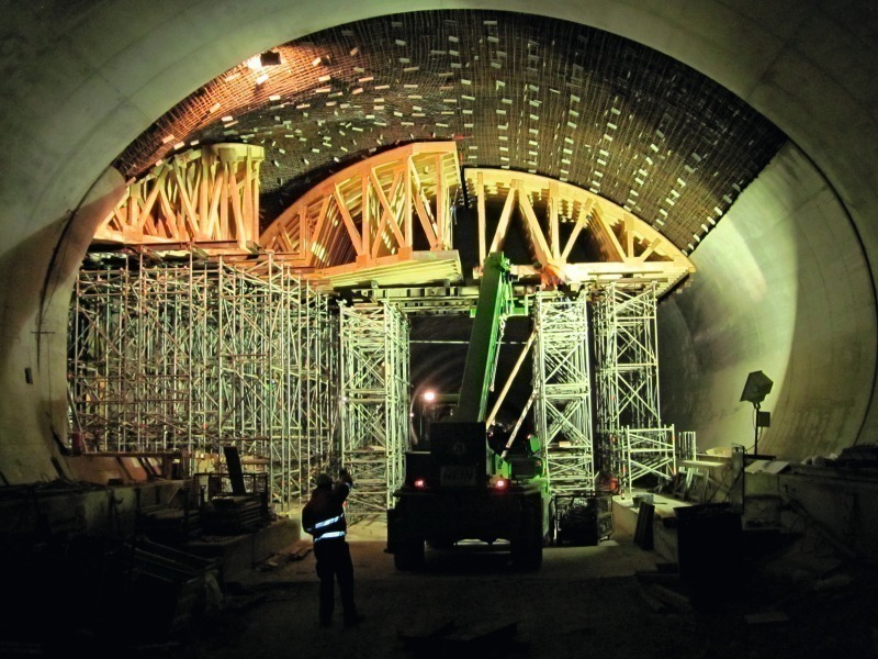 Photo: Huber & Sohn
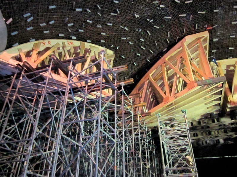 Photo: Huber & Sohn
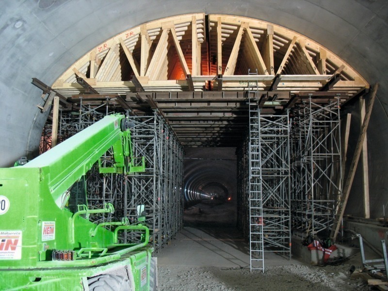 Photo: Huber & Sohn
The Jagdberg Tunnel, under construction near the city of Jena, is part of the project for widening of the heavily frequented A4 autobahn in Thuringia. This article focuses on the sophisticated formwork technology used.
A section of the heavily frequented A4 autobahn in Thuringia is undergoing widening via the new twin-bore Jagdberg Tunnel. The client, Deutsche Einheit Fernstraßenplanungs- und -bau GmbH (DEGES), entrusted this work to the Tunnelbau A4 consortium, consisting of Baresel and ALPINE BeMo Tunnelling.
Virtually immediately upon its opening to traffic in 2013, this new six-lane tunnel will be used by around 80,000 vehicles every day. The two bores are each around 3,100 m in length.
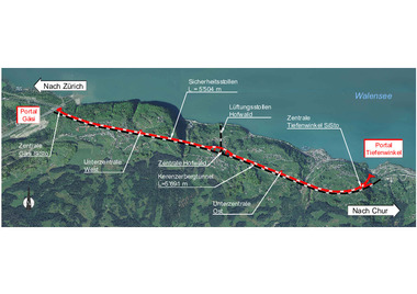
Approval for the passage of hazardous goods is vital for this tunnel project, and for this reason an approx. 140 m deep centrally located smoke-extraction shaft was included as early as the planning stage (Figure 1). In case of fire, the smoke and fumes generated will be drawn vertically upward via this shaft. Corresponding louver panels make it possible to extract smoke separately from the two bores. In accordance with the RABT code, emergency lay-bys are provided every 550 m, and transverse escape tunnels every 275 m, to assure the safety of tunnel users.
Special formwork system
The planning for the transverse smoke-extraction gallery originally envisaged a transverse tunnel of horse-shoe configuration (Figure 2) leading via a 90° connection into the main tunnel bores at an acute angle and then joining the vertical smoke-extraction shaft.
In order to optimise the fluid dynamics of this sector, the client decided to substitute laminar curves for the transitional zones in the intersection. The curve radius between the shaft and the transverse smoke-extraction gallery (Figure 1, marked in green) will be a constant 1.0 m; the rounded transition (Figure 1, in blue) into the main tunnel will have a variable radius, since two totally different geometries converge here.
These requirements were to form the basis for an extraordinary formwork-technology challenge. For this purpose, Huber & Sohn, of Bachmehring, were consulted at an early stage by the consortium of contractors, which had been awarded the work on the basis of the complexity of the project and its own relevant experience.
Working schedule
The complicated design and a range of diverse boundary conditions (including the making of the self-supporting reinforcement throughout the intersection zone) necessitated, from an operational and formwork-production viewpoint, a concept thought out and planned in exceptional detail.
The entire junction area is located in a difficult geological fault zone at a point of transition from the Roethian to Muschelkalk. This resulted, due to the known poor rock mechanical properties, in extremely high reinforcement contents, of up to 400 kg/m³ at some points. The element thicknesses, of > 1.0 m in some cases, combined with a reinforcement content which is extremely high for a tunnel structure, meant that adequate compaction of the concrete using external or formwork vibrators could not be assured. For this reason, the consortium decided, with the approval of the client, in favour of the use of self-compacting concrete (SCC).
It was therefore necessary to design the entire customised formwork system for the fresh concrete load generated by SCC.
The following procedure was agreed with the client: the first implementation phase would necessarily be the excavation of the shaft bottom (Figure 3); this consists of the base, the central section of the smoke-extraction gallery, complete with a vault for a transformer bay (Figure 1, red) and the connection to the smoke-extraction shaft (of 6.70 m diameter, see Figure 4). The total height of the formwork from the base up to the top end at shaft ring level was around 9.50 m.
It was necessary at the start to define the geometry of the transverse gallery and, in particular, the execution of the curved transition between the vaulted roof of the transverse gallery and the shaft ring. The formwork manufacturer was then able to start preparing for the work, and to begin planning for production of the formwork elements.
A so-called „A-structure“ was selected for the formwork for the shaft basement, which was to be used only once. The formwork elements were produced in their full height, permitting their connection to one another at the roof end. The arched elements were braced against one another in the horizontal; either one or two bracing elements were used, depending on size and statics. Adhesive anchor bolts were installed in the existing base to counteract buoyancy forces. It was necessary to brace the elements, which were produced in widths suitable for transportation (i.e., up to 3.00 m), with one another across their entire length by means of formwork ties. The two end formwork sections were then also fixed to this anchoring system.
An adequate number of nozzles were provided for installation of the concrete. Concreting windows were also made in the formwork elements to permit observation, and were successively closed as concreting progressed. The entire operation of filling the formwork was monitored, and the exertion of excessive pressure on the formwork by the closing force avoided, by means of so-called „peepholes“ in the roof.
Measurements performed during concreting indicated fresh concrete pressures of up to 90 kN/m² and above. The maximum measured deformations of the reinforced formwork nonetheless remained in the millimetre range.
Installation of the special formwork system in the main tunnel started immediately, once the centre section of the transverse smoke-extraction gallery (shaft basement) had been completed.
A new concept was jointly developed for these two trumpet-shaped flares. The greatest difference was the fact that the vaults were not created in a single operation, but were, instead, divided horizontally into the side zones (wall) and crown (roof) formwork. The following factors spoke in favour of separate formwork here:
Formwork across the entire length of almost 15 m and the entire width of over 16 m from the outer edge of the main tunnel to the junction with the transverse smoke-extraction gallery would have necessitated excessive fitting and installation work. Another critical point was the fact that an enormous single-face concreted component would have resulted, via the opening of the transverse gallery, and could have been mastered only with enormous technical input. This decision proved, in retrospect, to have been absolutely correct.
After successive fabrication of the various customised formwork arrangements, work began on the formwork shuttering for the approx. 15 m long and approx. 5 m high side-zone of the north bore (Figure 5). The side-zone formwork, lined with alkus GM 6 formwork facing, was held in place by means of support trestles, which were themselves re-anchored using rock bolts of 26 mm thickness in the benches. It was necessary to underpin the trestles by means of a separate steel structure of around 1.00 m in height at the rear support point, since this work was being conducted on an invert arch floor.
Assembly and removal of the formwork were completed without difficulty, as was concreting using SCC. As in the case of the shaft basement, the resultant concrete surface was extremely satisfactory.
Following this relatively simple deployment, the two side-zone formwork systems, complete with curves, were re-erected closer to the transverse smoke-extraction gallery (Figure 6). The surfaces here feature double curvatures, and could therefore not be produced using a conventional formwork panel. Even the planning and production work on the formwork for the substructure was greater by a multiple. The formwork is required here to perform a smooth transition from the geometry of the main tunnel to that of the transverse smoke-extraction gallery and - as if this task were not already sufficiently demanding - a transition on a radius which, at around abutment line height was, on paper, 4.50 m; above and below this level, it was necessary to determine the radius empirically.
Due to this exacting geometrical situation, a substructure utilising a horizontal trestle construction was selected. A double, 20 mm thick, wooden panel was chosen as the formwork facing, in order to permit the creation of the in some cases pronounced curvatures and convolutions as accurately as possible. „Double“, because the radii in question could not have been implemented using a single wooden panel - the boards would have failed. A further advantage of a double formwork facing is provided by the overlapping of the board joints, which keeps the formwork tight, a factor which naturally plays a decisive role in the context of SCC. The option of a rabbet technique, such as tongue and groove, for example, was not available, since the boards were cut with a „waist“ geometry, similar to the staves of a barrel. The surfaces were then finished by means of grouting, smoothing and painting.
Detailed advance planning by the formwork manufacturer was necessary for the formwork for the two curvatures, since restraint of the formwork using support trestles was again required, and collision of the trestles with one another upon their convergence in the vicinity of the transverse smoke-extraction gallery had to be avoided.
These two sectors of the side-zone formwork systems were also concreted without difficulty using SCC, with results with which all parties, after stripping of the formwork, were extremely satisfied.
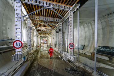
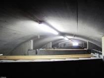
Finally, the top formwork for the main tunnel, complete with the intersection, was made (Figures 7 and 8). This formwork had to be erected in one piece for the entire length of main tunnel, i.e., some 15 m, with a width of around 20 m. This deployment also demanded detailed scheduling, since the large number of elements (Figure 9) were to be installed in a precisely defined order (Figures 10 and 11). Adherence to the planned schedule was vital, in view of the enormous size of the intertwined elements at the junction of the main tunnel and the transverse smoke-extraction gallery. It also had to be ensured during the installation work that normal site traffic could pass through the formwork (Figure 12). The worksite was scheduled to transit this sector with the complete string of formwork carriages at a fixed time and date, and all work on the intersection zone was therefore timed to meet an extremely critical deadline. The final section of the north bore was also completed on time and to the total technical satisfaction of both the consortium and the client.
Huber & Sohn and the Tunnelbau A4 consortium will begin work on the second side in early 2011.