Steel-fibre-reinforced segmental linings:
State-of-the-art and completed projects
Steel-fibre-reinforced concrete is a material widely used in tunnel engineering. The following article is to presented as a paper at the Second Herrenknecht Formwork Technology Days in early March, 2011. It examines the current state-of-the-art in the use of steel-fibre-reinforced concrete for segmental linings and outlines a number of practical examples.
Introduction
Upon the appearance of steel-fibre-reinforced concrete on the European market in the 1970s, neither standards nor guidelines for the design and dimensioning of this new material were available. Steel-fibre-reinforced concrete was initially used as a substitute for nominal reinforcement or in combination with conventional reinforcing steel, in order to enhance the serviceability of concrete structures. Once experience with this building material had been gained, significant progress was made in terms of codes and guidelines, both nationally and internationally, and for a large range of diverse applications, in order to provide well-founded aids for the design, testing, production and installation of steel-fibre-reinforced concrete.
Steel-fibre-reinforced concrete finds one of its most prominent applications in tunnel construction. The frequently encountered stress-resultant combination of high compressive forces and relatively low bending moments in a tunnel lining can predominantly be matched by using the material properties of steel-fibre-reinforced concrete only. The material‘s resistance against concentrated loads assures a remarkably low maintenance costs. The use of this material simplifies the construction process and accelerates the speed of execution. Interest in the use of steel-fibre-reinforced concrete in tunnel construction is rising as a result of the flexibility which the use of this material permits and the cost-savings achieved compared to the use of conventional reinforced-concrete solutions. Assessment at international level indicates that reference projects using steel-fibre-reinforced concrete as a permanent load-bearing support element remain far too rare in Germany. There is no technological justification for this omission, in view of the fact that both theoretical and practical experience is available. With the introduction of the German Guideline „Steel fibre reinforced concrete“ [2] by the German Committee of structural concrete (DAfStb) an extensive tool with full character of a standard will be provided for Germany.
2 The advantages and materials properties of steel-fibre-reinforced concrete
Steel fibres are mixed into the concrete in order not only to achieve an increase in load-bearing capacity, but also to improve mechanical properties in specific areas. Decisive properties which are significantly improved by the addition of steel wire fibres include:
• Ductility in tension and in compression
• Impact resistance
• Fatigue resistance
• High resistance against spalling
• Durability
• Low crack widths under service conditions
• Flexural strength in all three directions.
The replacement of conventional reinforcement by steel fibres also assures cost-savings potentials for reinforcement work (production, storage and installation of the reinforcement cages) and enhances flexibility in case, for example, of project modifications.
3 Applications for
steel-fibre-reinforced concrete in tunnel engineering
The potential uses for steel-fibre-reinforced concrete in tunnel construction are many and diverse. This, naturally, is also the reason behind the large number of existing application variants. Tunnel-construction methodology, which now differentiates between shotcreting and mechanised tunnelling, should firstly be examined. Further more it can be distinguished between single-shell and double-shell types, Steel-fibre-reinforced concrete is used in all these variants.
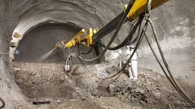
In the case of steel-fibre-reinforced concrete for shotcrete, the steel fibres are added to the basic shotcrete concrete mix. The decisive advantage of the ability to omit the „installation of reinforcement“ operation is the predominant benefit of the shotcrete method. Not only is completion time foreshortened, early activation of initial ground support - a factor particularly critical under difficult geological conditions - is also assured. Early application of the initial support, combined with the strength of steel-fibre-reinforced concrete at young age, reduces ground disintegration phenomena and, as a corollary, also overburden pressure, achieving a significantly better stress state.
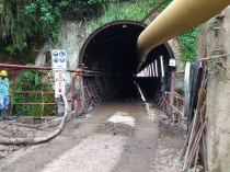
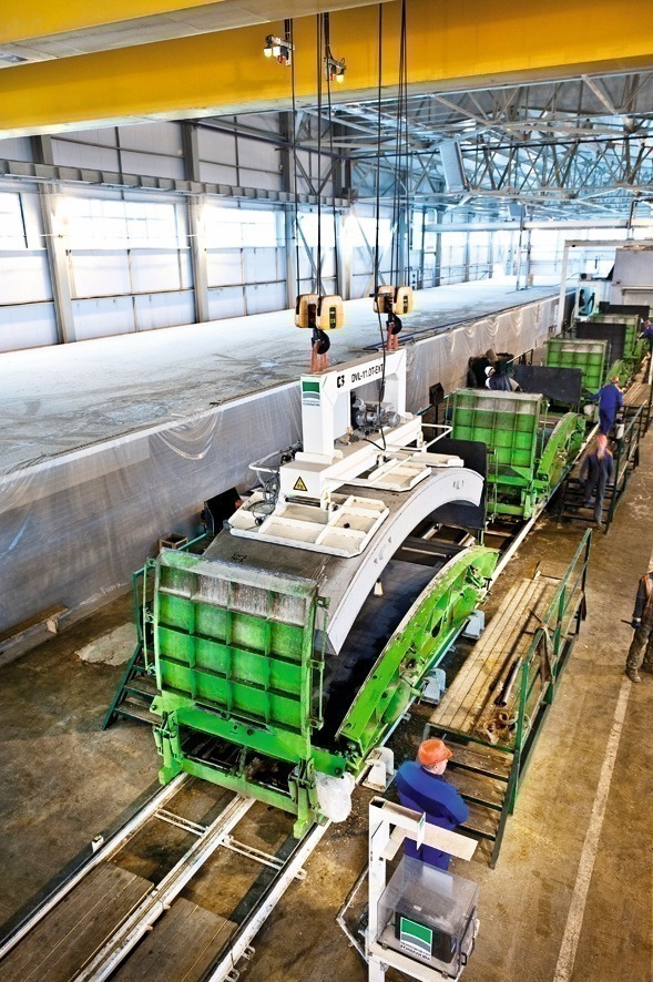
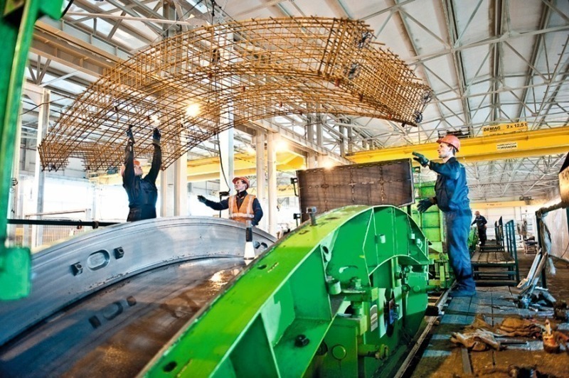
Factory-produced segmental lining transported to the site are generally used in mechanised tunnel construction. These segments are installed as support behind the shield machine and produce a closed annular ring which, in the case of single-shell lining, is also not further supplemented. Using steel-fibre-reinforced concrete, load states resulting from formwork removal (Figure 1), storage and transportation can generally be taken up without any additional reinforcement. The bending stresses occurring are generally low. The advantage of the use of steel-fibre-reinforced concrete here is already obviously; there are no costs resulting from the provision and storage of reinforcement cages, no reinforcement work is necessary, and the entire working process is thus accelerated (Figures 2 and 3).
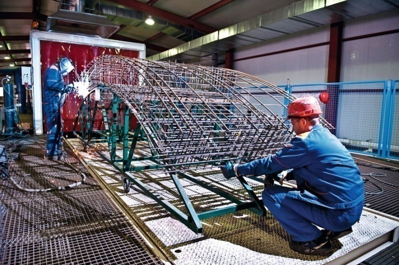
Joints are particularly critical points. Spalling phenomena are caused by transportation and mainly by installation, and cannot be prevented when traditional reinforcement is used as a certain concrete cover needs to be provided to protect from corrosion risks (Figure 4). Serviceability is negatively affected if such spalling results in water-permeability. The advantage of steel-fibre-reinforced concrete segments over conventional reinforced concrete is that fibres are dispersed all over the section and hence the concrete is also there needled where those critical corner and edge zones are to be found. Conventional reinforcement can be omitted entirely in cases in which load-bearing capacity is assured by the steel fibres alone. If a fire occurs, the steel fibres prevent the peeling off of surface layers. And, in case of combination reinforcement, for example, the rebar reinforcement is better protected.
4 Effectiveness in
segmental linings
Essential properties of steel-fibre-reinforced concrete are its ductile material behaviour and its ability, in case of cracking, to assure load transfer across the crack. Of particular importance is the fact that steel-fibre-reinforced concrete with usual fibre contents is equivalent to a sub-critical reinforcement. It is therefore primarily used in elements which permit redistribution of internal forces, and therefore multiple crack-formation (i.e., statically indeterminate stuctures).
Tunnels are highly statically indeterminate systems. The load combination of bending moment and compressive normal force is governing for the design in the ultimate Limit state. The stiffer the systems, the more greatly they attract bending moments. The higher the moments occurring, the greater the necessary degree of reinforcement. Flexible systems, on the other hand, bear the loading by means, primarily, of normal forces. This is, therefore, the rationale for the demand for flexible systems in modern tunnel construction. Unlike the situation with stiff systems, the deformation of the shell causes intensified activation of the ground‘s own load-bearing function. The forces to be absorbed by the support (segmental lining rings) are therefore lower in the case of ductile systems. The materials properties of steel-fibre-reinforced concrete are suitable in two ways for meeting the required load-bearing capacity:
1. Enhancement of cross-sectional load-bearing capacity
Steel-fibre-reinforced concrete in cracked condition remains capable of transferring Loadings and taking up forces. Unlike the situation with non-reinforced concrete (mathematical assumption of tensile forces not allowable), this results in a significant increase in load-bearing capacity in structures exposed to bending requirements with normal forces. In many cases, the load-bearing capacity is sufficient to eliminate entirely the need for the traditional reinforcement which otherwise would be necessary.
2. Enhancement of system load-bearing capacity
Once the initial cracking load has been exceeded, steel-fibre-reinforced concrete‘s ductile material behaviour permits transfer of forces to other cross-sectional elements; stresses are redistributed till the final load-bearing capacity of the system is obtained. Plastic analysis comprises the load-bearing capability of steel-fibre-reinforced concrete most rationally. The resulting stressess determined on this way are lower than in the case of a purely elastic analysis. In addition, the load taken up borne directly by the rock itself is also increased in the case of more flexible systems.
5 Criteria defining the performance of a steel-fibre-reinforced concrete
Concrete is classified by its strength in compression. It is of (almost) no significance how much cement and which aggregate and additives are used to achieve a particular compressive strength - cement is not just cement, and aggregate is not just aggregate! This adage is also true of fibre-reinforced concrete since, here too: fibres are not just fibres! Steel wire fibres are produced from cold-drawn wire of various steel grades. Their tensile strength is generally between 1,000 N/mm² and 2,500 N/mm²; fibre lengths vary between 30 mm and 60 mm, their diameters between 0.40 and 1.10 mm. The performance of steel wire fibres and, therefore, of the resultant steel-fibre-reinforced concrete, depends essentially on fibre diameter, fibre length, fibre anchorage, wire tensile strength and delivery form. The criteria listed below assure a high-performance steel-fibre-reinforced concrete:
• Hooked ends
• As thin as possible
• As long as possible
• High slenderness
• Tensile strength appropriate to the strength of concrete
• Optimised concrete recipe.
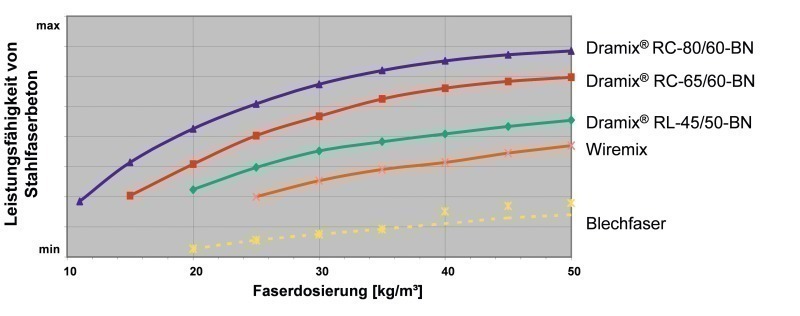
Three different types of steel fibre illustrate, by way of example, the running-meter length and number of fibres for 1 kg. The l/d quotient states the length:diameter ratio and thus a form of performance classification (Figure 5).
RL-45/50-BN⇥l/d = 45 L = 147 m/kg⇥
2,950 fibres/kg
RC-65/60-BN⇥l/d = 65
L = 200 m/kg
3,330 fibres/kg
RC-80/60-BN⇥l/d = 80
L = 288 m/kg
4,800 fibres/kg
The longer the fibres and the higher their number, the greater the probability that a crack will cross a fibre! Glued bundles of fibres also permits extremely high-performance fibres of great slenderness (l/d > 50) distributed uniformly in the concrete. Also decisive is the selection of a tensile strength appropriate to the strength of concrete, in order to maintain the ductility of the steel-fibre-reinforced concrete. Steel wire fibres of standard tensile strength (1,000 to 1,300 N/mm²) are generally used for concretes of the strength classes up to C 50/60. Medium- or high-strength steel wire fibres (1,500 to 2,500 N/mm²) are recommended for higher strength classes.
6 Test procedures for determination of performance
6.1 Preliminary note
Test specimen are generally tested by means of deflection-controlled test setups. It is possible to differentiate in principle between statically determinate beam tests and statically indeterminate panel tests. Statically determinate beam tests are used for the determination of materials properties. The flexural tensile strength determined after cracking is used as a characteristic value on the material-resistance side for dimensioning of segmental-lining elements. The fundamental principles of beam tests are examined in the following sub-section. The probably most widely used panel test, the „EFNARC panel“, is subject to a verification procedure for determination of system load-bearing capacity. The square panel positioned on all sides is statically indeterminate and simulates the load-bearing behaviour of a shotcrete shell. System load-bearing capacity is evaluated as energy-absorption capacity, and set against the requirements made on the shotcrete layer. Since this panel test determines a system load-bearing capacity, the result cannot be used for the dimensioning of individual elements (e.g. segmental support rings). The panel test is not examined in any more detail in this article.
6.2 Statically determined beam tests
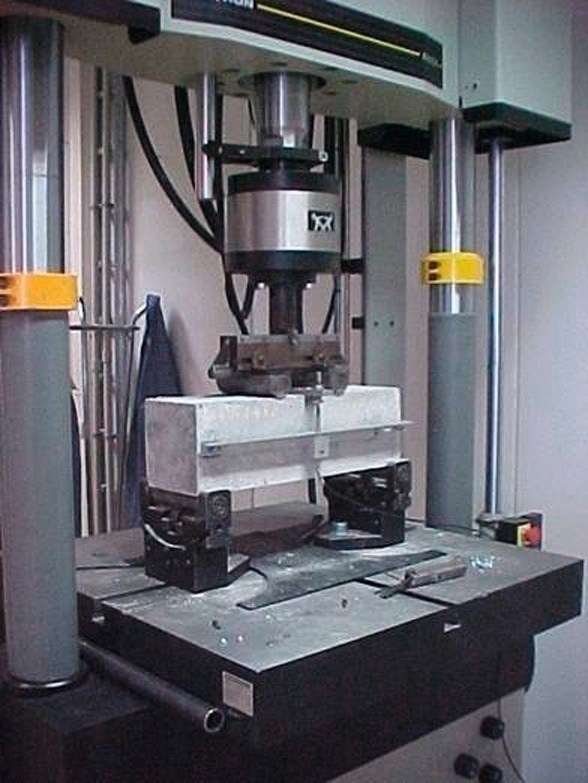
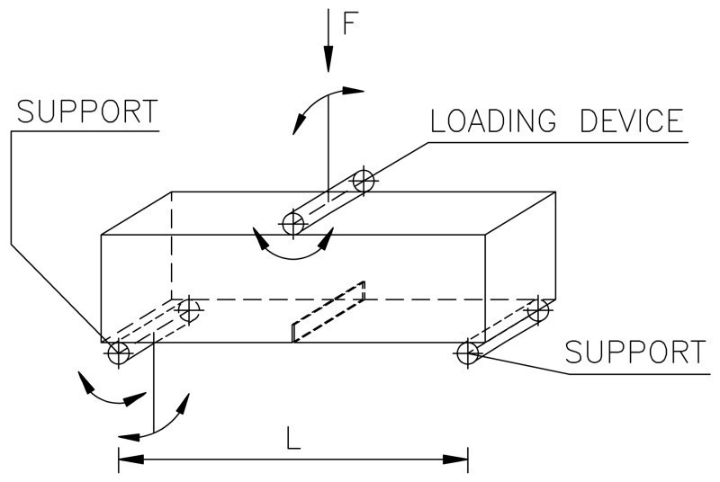
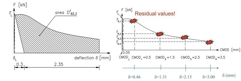
Determination of materials properties to reveal the bending moment capacity is performed by means of deflection-controlled beam tests. The test procedure utilising statically determinate test beams provides a method suitable for conversion of the results to a design (for cross-sectional capacity in the various states of construction, or for the M-N interaction diagram, for instance). The EN 14651 test method [4] issues a three-point bending test (Figure 6, right). The load/deflection curve is evaluated by means of residual values at defined deflection points. The JSCE SF‑4 test procedure [6] issues a four-point bending test (Figure 6, left). The load/deflection curve is evaluated on the basis of equivalent values (evaluation of the area below the curve). The German society of concrete (DBV) recommendation [3] and the DAfStb guideline for steel-fibre-reinforced concrete [2] also foresee a four-point bending test. The evaluation methods differ, however. Two deformation zones are generally evaluated. Performance at low beam deflection is used for analyses in serviceability limit state. Performance at greater beam deflection is utilised for analyses in the ultimate limit state (Figure 7).
6.3 Full scale tests
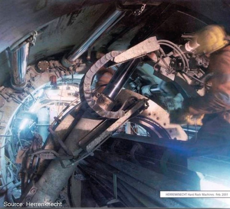
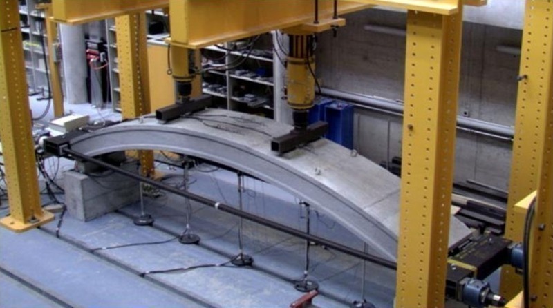
By means of the available calculation methods it is sometimes hardly possible to fugure out the ultimate material resistance, particulary if such elements are exposed to bursting and spalling forces. The ultimate load-bearing capacity of the material used can therefore be determined extremely well by means of experimental tests (Figure 8).
7 Codes and standards for steel fibres
7.1 Codes
A code has been available in Germany for the dimensioning of steel-fibre-reinforced concrete elements up to now, in the form of the DBV „Steel-fibre-reinforced concrete“ recommendation [3]. This is based on the DBV „Tunnel Engineering“ recommendation but also includes European developments in the field of standardisation. The DBV „Steel-fibre-reinforced concrete“ recommendation [3] provides a well founded aid to the dimensioning of steel-fibre-reinforced concrete. This code does not have the character of a standard, however. In view of this fact, the DAfStb dicided to draft a guideline orientated around DIN 1045-1. The final edition of the DAfStb „Steel-fibre-reinforced concrete“ guideline [2] was published in March, 2010. This guideline replaces and complements parts of DIN 1045-1 and after being taken up in the List of building materials ist has a status of a code. Rules of dimensioning for steel-fibre-reinforced concrete have also been drafted in neighbouring European countries; here, Switzerland may be mentioned, with its Recommendation SIA 162/6 [10], also Austria, with its „Fibre-reinforced concrete“ guideline [8], and the Netherlands, with the CUR rules and RILEM, in which Technical Committee TC 162 has set out recommendations for the testing and dimensioning of steel-fibre-reinforced concrete under the title „Test and Design for Fibre Reinforced Concrete“. Steel-fibre-reinforced concrete has also been included in the FIB Model Code 2010 [7].
7.2 Standardisation of steel fibres
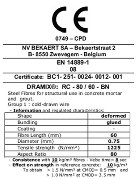
In Europe, steel fibres for use in concrete must be marked with the CE symbol. The minimum requirements for steel fibres are defined in the harmonised DIN EN 14889, Part 1 [5] standard. DIN EN 14889, Part 1 [5] defines requirements for steel fibres for concrete, mortar and grouting mortar for load-bearing and other purposes. There are two different systems for certification of conformity: „System 1: Steel fibres for load-bearing purposes“ and „System 3: Steel fibres for other purposes“. DIN EN 14889, Part 1 [5] defines „load-bearing purposes“ as follows: „When fibres are used for load-bearing purposes, the fibres added contribute to the load-bearing capacity of a concrete element“. Certification of conformity in accordance with „System 1“ is therefore required for virtually all cases of practical relevance. To eliminate the possibility of mistakes, only steel fibres controlled and certified in accordance with „System 1“ and bearing the corresponding EC certificate of conformity should be used. Permissible tolerances for the main properties of the fibres in each case are issued in the standard. The influence of the fibres on the strength of concrete is tested on a reference concrete, in order to provide the user with an idea of the performance of individual fibre types. The minimum steel fibre content necessary to achieve a residual flexural tensile strength of 1.5 N/mm² with a crack width of 0.5 mm, and of 1.0 N/mm² with a crack width of 3.5 mm, in a test procedure in accordance with DIN EN 14651 [4], is defined. The amount of fibres need to be declared to abtain these performances. That provides reference of the performance of individual fibre types (Figure 9).
8 Reference projects
Numerous tunnel projects around the world have been implemented using steel-fibre-reinforced concrete segmental linings in recent years. A number of these projects are summarised as follows.
Channel Tunnel Rail Link
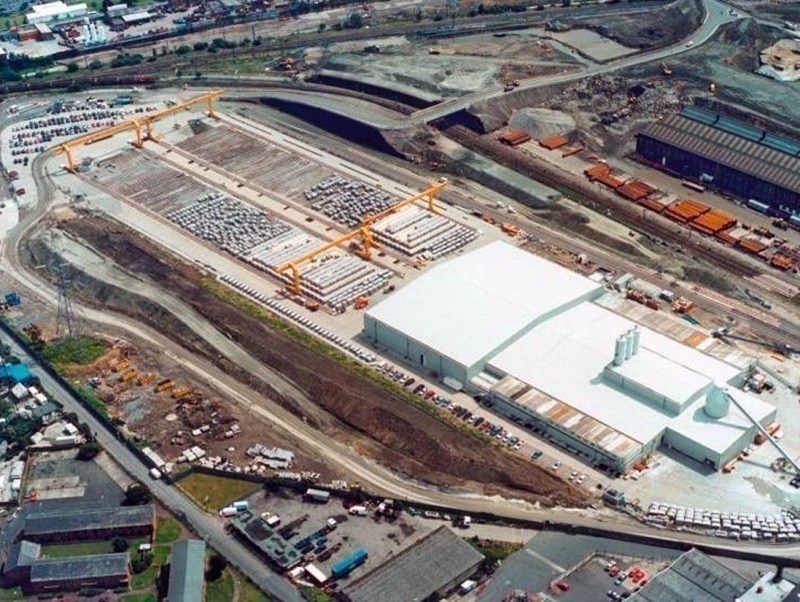
The CTRL (Channel Tunnel Rail Link) is the tunnel connecting Britain and France. This project was completed in the 2003 to 2004 period. A total of 200,000 individual segments were produced in a temporary prefabrication facility to supply the project (Figure 10). Each ring consisted of nine segments plus a keystone, for an inner diameter of 7.15 m and a lining thickness of 350 mm. Extremely demanding durability requirements were defined in the invitation to tender for this project. A material resistant to aggressive environment conditions was to be used, and a service-life of 120 years to be indicated for the segmental tunnel lining rings. The concept of using a high-performance steel-fibre-reinforced concrete was, therefore, a relatively obvious step. The steel-fibre-reinforced concrete used contains Dramix RC-80/60-BN steel wire fibres. The number of individual segments which required replacement or retrospective repair due to damage was exceptionally low, on the basis of empirical data for conventionally reinforced segmental lining systems.
Oenzberg Tunnel
The Oenzberg Tunnel is the key engineering work on the new Bern-to-Zurich line, constructed as part of Switzerland‘s „Rail 2000“ project. This double-track, 3,160 m long tunnel was driven using a mix-shield tunnel-boring machine. The use of steel fibres provided an elegant and rapid solution, since production of segments was scheduled to start in a short time. Tests using ultra-modern equipment were performed in the context of this construction project, in order to investigate the performance of the segmental lining, and of the segment joints, in particular, under the load conditions prevailing in the tunnel. The following types of reinforcement were comparatively assessed:
• Purely steel-fibre reinforcement
• Combined reinforcement (steel fibres and reinforcement meshes)
• Conventional reinforcement (reinforcement meshes and rebars).
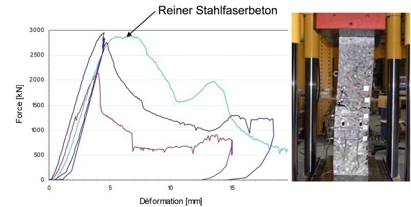
Figure 11 illustrates the ductile material behaviour of steel-fibre-reinforced concrete under compressive loading. In addition, the same load level as with the conventional reinforcement alternative was also achieved.
The Hofoldinger Stollen
In Germany, a 17.50 km long tunnel project using segmental lining consisting entirely of steel-fibre-reinforced concrete was implemented in the form of the construction of a drinking-water supply conduit from the Mangfalltal valley (Figure 12). The „Hofoldinger Stollen“ was constructed between 1999 and 2004. The segmental lining ring, consisting of six segments with a diameter of 3.30 m, has a lining thickness of 180 mm and was fabricated using 40 kg/m³ of Dramix RC-65/60-BN steel fibres. The use of steel-fibre-reinforced concrete significantly accelerated the construction process. The problems of spalling at edges and corners, otherwise frequently encountered on individual segments, were satisfactorily suppressed.
The Wehrhahn Line, Düsseldorf
The Wehrhahn Line, in Düsseldorf, provides a further reference project in Germany. The 3.4 km long Wehrhahn Line is to be completed by 2014, with no less than six new underground stations. The steel-fibre-reinforced concrete lining segments are being used as temporary support for the station bores for a service period of three years. The tunnel bores have an outer diameter of 9.20 m. Each tunnel ring consists of 7+1 segmental ring lining elements. Element thickness is 450 mm. The static analyses were performed in accordance with the DAfStb „Steel-fibre-reinforced concrete“ guideline. The steel-fibre-reinforced concrete was batched using Dramix RC-80/60-BN steel fibres. Continuous quality control is being done to check the performance at defined intervals. Beam tests for verification of performance, and wash-out tests for continuous monitoring of uniform fibre distribution is foreseen.
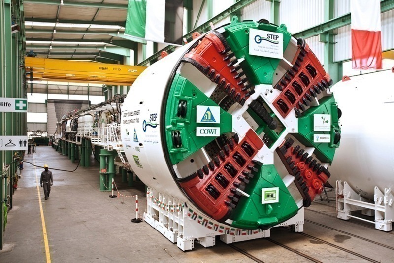
STEP, Abu Dhabi
One of the most recent major projects to include on-site segment production started in 2010 with the STEP tunnel project in Abu Dhabi. The planning here envisages a waste-water tunnel of a total of 42 km in length, with the work subdivided into three lots. Lot T-02, with a length of approx. 15.6 km, is currently undergoing implementation and is to be completed by the summer of 2012 (Figure 13). A double-shell variant (non-reinforced inner shell as the „final lining“) is planned. The tunnel bores are of 6.30 m diameter, while the individual segmental lining elements have a thickness of 280 mm. The drafting of the concrete recipe was a real concrete technology challenge, since it was necessary to meet both elevated durability requirements and to counteract the aggressiveness of the groundwater in the geology. A steel-fibre-reinforced concrete variant was selected, in order to improve durability and minimise proneness to spalling, and thus eliminate permeability from the inception. Local additional reinforcement was incorporated along the transverse joints, in view of the extremely high tensile splitting forces occurring at the connecting points of the individual segments. Design of the steel-fibre-reinforced concrete lining segments was otherwise in accordance with the DBV code [3]. The critical load case in serviceability limit state was determined. The necessary tensile strength after cracking required according the rules of the DBV code, of 1.6 N/mm², was achieved using a Dramix RC‑65/60‑BN steel fibre type, and confirmed by means of beam tests.
References
[1] Bemessung von Stahlfaserbeton im Tunnelbau, B.Maidl, A.Nitschke, M. Ortu, Bochum, June 1999
[2] DAfStb-Richtlinie Stahlfaserbeton, March 2010 edition
[3] Deutscher Beton- und Bautechnik-Verein e.V., DBV-Merkblatt Stahlfaserbeton, October 2001 edition
[4] EN 14651, Prüfverfahren für Beton mit metallischen Fasern – Bestimmung der Biegezugfestigkeit (Proportionalitätsgrenze, residuelle Biegezugfestigkeit)
[5] EN 14889-1, Fasern für den Beton – Teil 1, Stahlfasern – Begriffe, Festlegungen und Konformität
[6] JCI, Test for flexural strength and toughness for fibre reinforced concrete, JSCE SF-4 Japan Concrete Institute, 1984
[7] Model Code 2010, First complete draft, Volume 1, bulletin 55
[8] Österreichische Vereinigung für Beton- und Bautechnik „Richtlinie Faserbeton“, July 2008 edition
[9] R. Suter, P. Buchs, Precast fibre reinforced tunnel lining segments, Experimental Study, Final Report, University of Applied Sciences, Fribourg, 2008.
[10] SIA 162/: 1999 Empfehlung Stahlfaserbeton