Half way of Construction of the Liefkenshoek Rail Tunnel
Since end of 2008 the biggest infrastructure project in Belgium is under construction as a Public Private Partnership project in the Antwerp sea port harbor area. The construction works are in full progress and first major milestones of the project were passed successfully on the way to connect the railway freight transportation from the left and the right bank of the River Scheldt in 2014.
1 Introduction
With reference to the first publication about this project in tunnel 7/2009 an update of status of the works on this infrastructure project is given after a little bit more than 2 years of construction time.
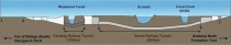
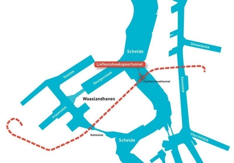
Figure 1 gives a schematic overview over the harbor installations with the new S-shaped Liefkenshoek railway link. In addition to the fact that trains will no longer have to leave the harbor territory, the operational costs for the trains will be lower due to the fact that the distance by rail between the major locations on left and right banks is reduced by approx. 22 km or 45 min of travel time.
The new rail way line follows for a major part in parallel the alignment of the existing highway R2, including the immersed Scheldt highway tunnel, which was built in the 1980’s. Furthermore, the restricted gradients of the slopes for railway tracks, which are much shallower than for roads, had to be taken into account.
This infrastructure project of approx. 16.2 km total length for railway freight is a Public Private Partnership project (PPP-project) with a maturity period of 38 years, ending in 2051 with the final handover to the Client Infrabel NV. After 2 years of tender, finally the successful bidder consortium LocoRail NV, composed of the Belgian company CFE NV, French company VINCI Concession SA and Dutch company BAM PPP, was awarded the DBFM-contract (Design, Build, Finance And Maintenance) as Special Purpose Company. The total invest of the project is 765 mio. Euro, whereas the value of the Design-and-Build-contract is 690 mio. Euro.
2 Building operations
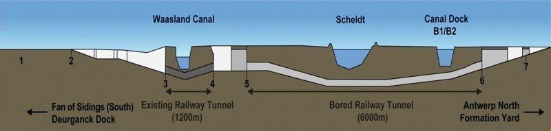
The project is divided into 13 construction parts, among others 2 culverts of in total 280 m length, an aqueduct across the track, 3 street and railway track crossings, the refurbishment of the existing, but never used 30 year old Beveren Tunnel below the Waasland canal, 4,300 m of water retaining slurry walls, 430 m of diaphragm walls, 2 shield driven tunnels of almost 6 km length as well as 8 evacuation shafts (ES), to be connected to the 2 tunnels and 13 cross-passages (CP) between the tunnel tubes (Fig. 2). In total almost 3 mio. m³ of earth moving has to be done, 400,000 m³ of concrete and approx. 40.000 t of steel have to be applied.
The joint venture THV LocoBouw, composed of MBG/CFE, BAM CEI-de Meyer, Vinci Construction Grands Projets and Wayss & Freytag Ingenieurbau AG, was awarded the building contract by LocoRail NV. MBG and BAM CEI-de Meyer are mainly responsible for the above ground civil works, Vinci and Wayss & Freytag as tunnelling experts are responsible for the shield-driven tunnels and the cross-connections.The execution of the project started in November 2008 on several parts of the jobsite, with the first milestones, the completion of the launching shaft to enable the installation and the start of the 2 each 100 m long Mixshield TBM. After successful assembly of the 2 TBM from Herrenknecht, Schanulleke, the North TBM, was launched successfully in February 2010. TBM South, Wiske, followed by end of March 2010, 7 weeks after Schanulleke.
In this article the focus will be set on the tunnel related works as the tunnel drive itself, the works in the Canaldock B1-B2, to be done before passing with the TBM, the works on the cross-passages (CP) and finally the connection-galleries between tunnels and the evacuation shafts (ES).
3 KW10 – The 5,970 m long TBM tunnels
The 2 tunnel tubes of each approx. 6 km length have an external diameter of 8.1 m and are constructed by 2 hydro-shield TBM with a diameter of 8.4 m. The thickness of the prefab tunnel segments is 0.4 m and the segments have a width of 1.8 m. The tunnel drives have a maximum inclination of 1.25 %. The minimum soil cover along the tunnel alignment is in the area of the Canaldock with approx. 3 m, which requires special measures in this area. The maximum overburden is approx. 33.6 m, the maximum water column above tunnel invert is approx. 40 m.
The geology in the tunnel cross-section consists of several tertiary sand layers of different local formations containing fractions of clay as well as glauconite, and the Boom Clay, a rigid, overconsolidated and fractured tertiary clay, as sealing layer beneath. Most parts of the tunnel alignment are situated in the tertiary sands, but the clay, which has a strong tendency to clogg reaches up to a maximum of 40 % of the tunnel cross-section for approx. 800 rings, which is equivalent to 1.44 km.
The 13 cross-passages between the tunnels will have to be done during the tunnel drive works, which has a big influence on the advance progress of the northern tunnel, from where most of the CP-works are started.
4 Passing the boom clay and crossing of the Schelde river
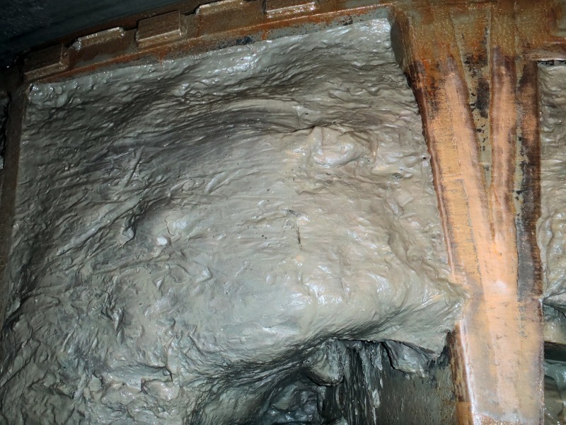
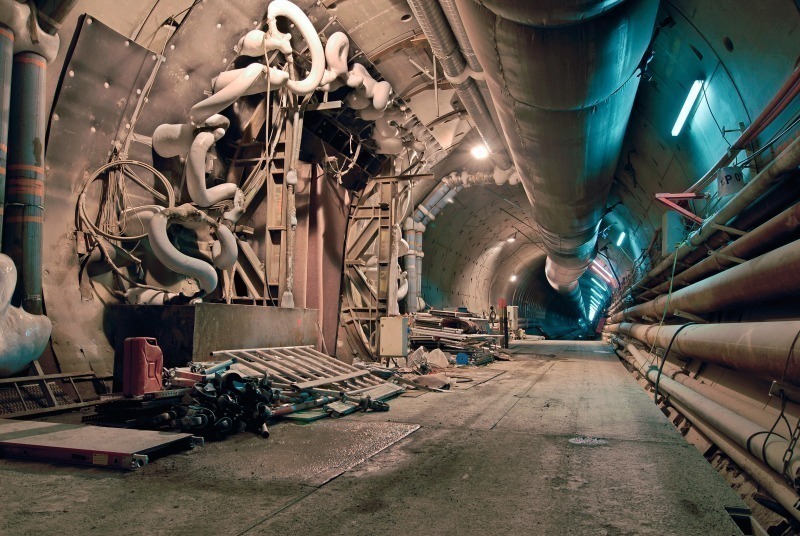
After a successful launching of both TBM the performance in the tertiary sands quickly reached a satisfying level of up to 75 rings per TBM per week. After approx. 800 rings the TBM started touching the Boom Clay in the invert zone. The advance speed dropped down to sometimes 1 or 2 rings per day due to the high grade of plugging of clay on the cutting wheel (Fig. 3).
At ES07, the 4th evacuation shaft along the tunnel drives, situated just in front of the Scheldt dyke, LocoBouw had build a maintenance box to exchange the cutting tools of the 2 TBM and to prepare the TBM to pass the 10.00 m long Scheldt river. TBM South, which had overtaken TBM North due to the CP-“stop-and-go-modus” left the box after 3 weeks of intensive maintenance and started to pass the Scheldt river. A 100 rings with clay at the maximum level had to be passed before the advance speed started to increase again. Finally Boom Clay was left after 1,700 rings.
TBM North arrived in the maintenance box end of October 2010. During the preparation to start the maintenance works under atmospheric conditions in the dewatered box, a failure in the sealing block in front of the cutting wheel was discovered. A cavern of 1.8 m length, 0.8 m width and up to 7 m height in front of the cutting wheel with flowing sand was discovered. Intensive reparation were done to refurbish the block and to start the maintenance works after a delay of 1 month. Finally the TBM North left the maintenance box by end of December 2010. With the experiences collected from TBM South regarding the manipulation of the clay and the crossing of the Scheldt river, TBM North advanced with additional 3 rings/day compared to the performance of TBM South in the Clay.
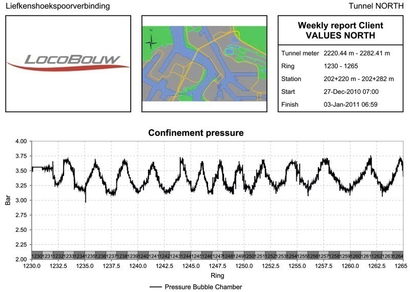
The Scheldt crossing was characterized by the low overburden of 9,7 m at the minimum and a river bed containing silt sedimentation and thick layers of disturbed sediment soil. In combination with the high water pressure of the Scheldt this lead to a very small gap between the minimum slurry confinement pressure and the blow-up-pressure, with 0.35 bar at its most critical cross-section. On top, the water level variation of the Scheldt, linked to the tides of the North Sea had to be taken into account. Every 6 hours the level in the Scheldt changes from minimum to maximum level and back. The peaks shift per day by ¾ of an hour. The regular variation of the water level is between +6.5 m TAW (Tweede Algemeene Wateraanpassing) and -1 m TAW, but also a spring tide with 2 m in addition had to be considered. As a consequence of the small gap between the decisive pressure levels and the quick change of water pressure, the slurry confinement pressure to support the front face had to be adjusted with a high frequency by the operators (Fig. 4).
LocoBouw tunnelling experts worked out a special procedure to ensure a safe crossing of the river even with the very small safety margin. The Scheldt river was divided into green, yellow and red zones, related to their level of severity and special measures were linked to the level of severity. Mid of February 2011, TBM North also finished successfully the Scheldt crossing by reaching the safe zone on the right bank, which was reached by TBM South in the second week of January 2011.
5 Passing of the Canaldock B1-B2
The second very critical part of the tunnel drives is the passage below the Canaldock B1-B2 due to the very low overburden of 1.1 m only, combined with the client’s requirement to keep the Canaldock free for traffic all the time. The upward incline of the alignment of the rail tracks was designed as steep as possible, to keep the tunnels as deep as possible. Nevertheless, the cover between the bed of the Canaldock and the tunnel crown is reduced to approx. 3 m. Due to the fact that the current soil in the Canaldock consists of a silt layer, which reaches down to maximum the axis of the tunnel, this soil had to be substituted.
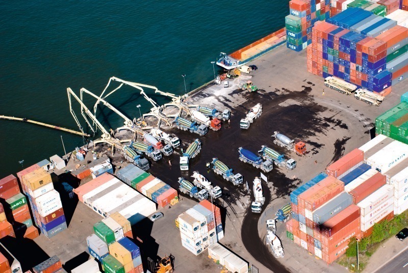
During detail design LocoBouw proposed a spectacular alternative design of the soil substitution combined with a 2.1 m thick steel-fiber-reinforced underwater concrete slab to reduce temporary backfill to a minimum section and to arise safety level during passage. In early 2010 LocoBouw constructed 2 rows of sheet piles besides the outer edges of the tunnel alignments in a depth of 18 m below water level. The silt inside the sheet pile pit of 270 m length and 35 m width, was excavated under water and substituted by 30,000 m³ of a mortar with low strength (Fig. 5). The pooring of the mortar was done in 4 days all day and night with a performance of 400 m³/h, keeping 4 batching plants and 120 mixers busy. After the substitution of the silt a 2.1 m thick steel-fiber slab was casted in October 2010 successfully on top of the mortar as a cover. The very sensitive steel fiber concrete was also casted during 4 days with an overall average performance of 290 m³/h. Both poorings were done via a pontoon fed from the banks of the dock, half from one side and half after turning the flowing pipes to the other side. Finally a temporary backfill with additional weight on top was installed at the change from the sloped bank to the steel fibre slab. The first TBM started the crossing of the Canaldock end of March 2011 after already 4.9 km of tunnelling.
6 Cross passages
As already mentioned, the CPs are constructed parallel with the tunnel drive works. This requires special solutions and high requirements on the organization and coordination of the works to reduce the interferences to an acceptable minimum. All CPs have to be constructed within a freezing body. At each CP a steel platform of more than 50 m has to be erected to start the works at the CPs and enable a permanent passing of tunnel logistics. The northern tunnel has to be blocked regularly to install the platforms and to execute the lower drillings of the freezing tubes. A special drill mast was developed together with the drilling subcontractor Rodio to perform more than half of the drillings of freezing tubes without any impact on the tunnel trucks. After the completion of the freezing of the soil, the tunnel lining, consisting from special reinforced concrete segments, has to be opened and the 8 m long excavation can start. Temporary shotcrete is applied before a sealing membrane system is applied to ensure water tightness. Finally the highly reinforced inner shell of the CP has to be constructed. Freezing tubes and a high amount of invert reinforcement in the portal areas require a very professional execution of the works to match the quality requirements and to stay within the program (Fig. 6).
7 Galleries to evacuation shafts
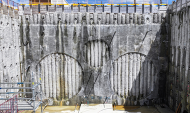
The tunnel tubes have to be connected to the evacuation shafts, constructed as rectangular shafts of diaphragm walls between the tunnels, by short but wide and high connection galleries. The 8 shafts are up to 40 m deep and only 3.4 m wide inside. The connection galleries are mainly done within treated soil by blocks of cement-bentonite with a low strength. Only 1 ES-connection will be done by freezing.
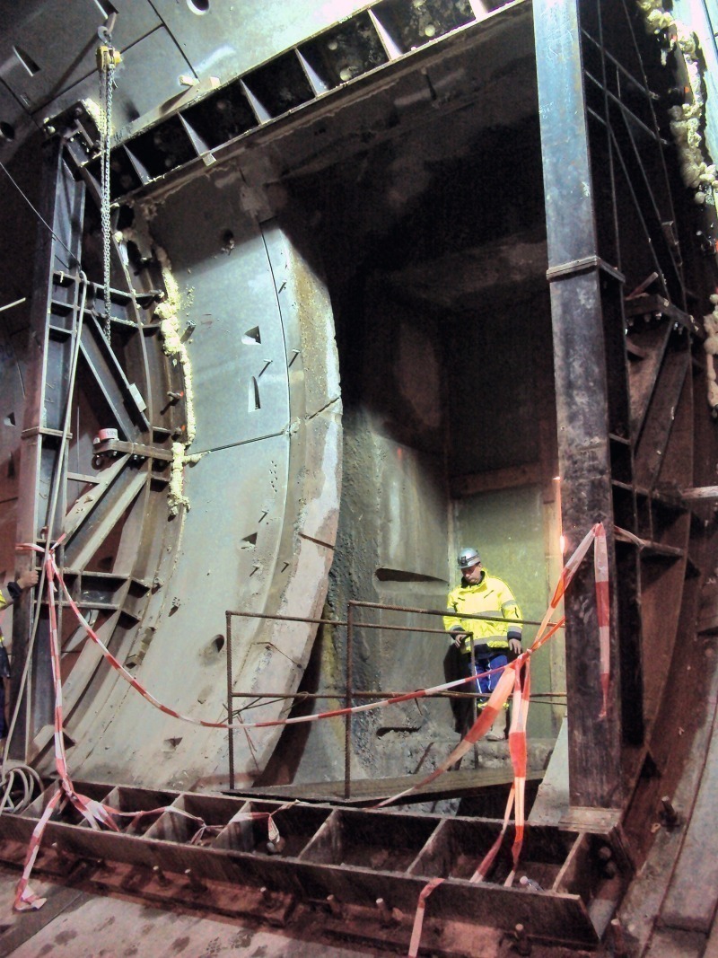
To construct the gallery, at first an opening of 3 x 4 m has to be cut into the 1.2 to 1.5 m thick d-walls to remove the reinforced concrete. Then the gallery excavation with a size of almost 6 m height has to be done within the water retaining sealing block. The distance to the external side of the tunnel lining is around 0.55 m in the tunnel axis level and up to 1.7 m in the invert. After protection with shotcrete, the tunnel lining is cut and partly removed. The final structure of the gallery is a composite construction of concrete and steel profiles.
At the moment 2 evacuation shafts are successfully opened and final structure is under construction. These evacuation shafts are used as emergency exits also during the construction time (Fig. 7).