Green Line Qatar: Conventional Tunnel Headings
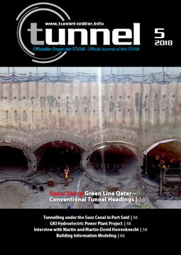
![Overview Green Line, Metro Doha, Qatar [3]](https://www.tunnel-online.info/imgs/1/3/5/8/3/1/2/Bild-1-ae0aa8f699128234.jpeg) Quelle/credit: Qatar Rail
Quelle/credit: Qatar Rail
 Quelle/credit: Porr AG
 Quelle/credit: WBI GmbH
 Quelle/credit: WBI GmbH
 Quelle/credit: WBI GmbH
 Quelle/credit: WBI GmbH
 Quelle/credit: WBI GmbH
 Quelle/credit: WBI GmbH
 Quelle/credit: WBI GmbH
 Quelle/credit: WBI GmbH
 Quelle/credit: WBI GmbH
 Quelle/credit: Porr AG
 Quelle/credit: Porr AG
 Quelle/credit: Porr AG
An extensive subway network is being built in Doha, Qatar. Part of this network is the so-called Green Line, for which also a number of underground street crossings had to be constructed. Originally, it was planned to carry out construction of these underpasses by means of the cut and cover method. Following a proposal of the contractors, three underpasses were, however, constructed by the mining method. Design and construction were executed on the basis of the AJRM-Method.
1 Introduction
The Green Line was built by a joint venture consisting of the contractors Porr, Saudi BinLadin Group and HBK [1, 2]. It runs from the starting shaft at Al Rayyan stadium in the West to the station Msheireb in the East (Fig. 1, [3]). The sections running in tunnels have a total length of 2 x 18.5 km, of which 2 x 16.7 km have been driven with tunnel boring machines [1, 3].
The two stations Al Messila and Hamad Hospital form part of the project. In order to guarantee access to the stations from the complete periphery, underpasses have been built underneath Al Rayan Road, an 8-lane road of major importance. Originally it had been planned to build both underpasses according to the cut-and-cover method. Due to the numerous cables and pipes and since traffic on the busy Al Rayan Road had to be kept alive, it was decided on the basis of a feasibility study of WBI to construct the underpasses according to the mining method though the height of overburden amounts to only a few meters and thus is rather small [2].
In view of the good experiences with design and construction of above mentioned underpasses according to the mining method, the client Qatar Rail agreed to apply the mining method also to
the construction of the vent tunnels for the Green and Red Line at Msheireb Station, instead of the originally foreseen cut-and-cover method. Design has again been elaborated by WBI on behalf of the Joint Venture Porr – Redco International. The present article gives a short overview on the design and execution of the ventilation tunnels.
2 Structure
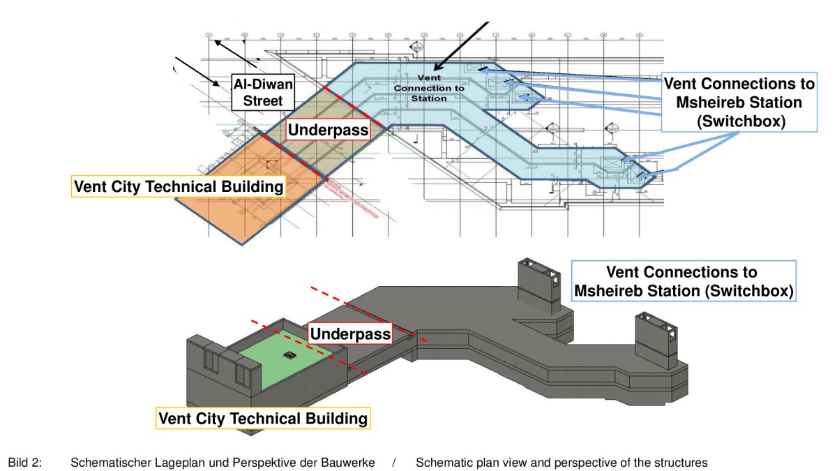
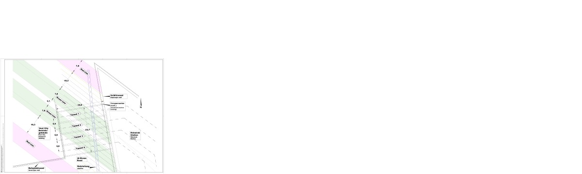
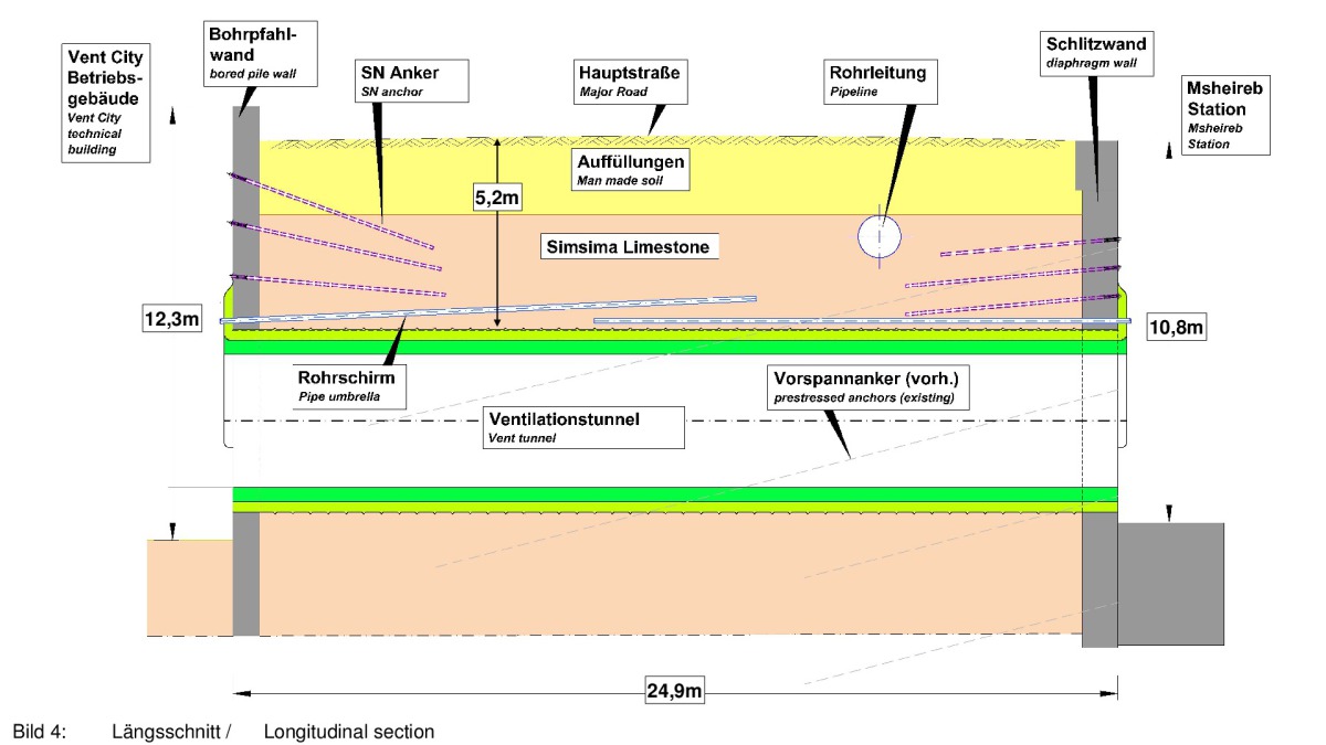
For the ventilation of the tunnels of the Red and Green Line, a technical building is constructed in the area of Msheireb station (Figs. 2 + 3). The connection between technical building and switchbox is realized with the aid of four ventilation tunnels crossing under the Al-Diwan Road. The vent tunnels are approx. 25 m long and have only ~5 m overburden height above the roof (Fig. 4).
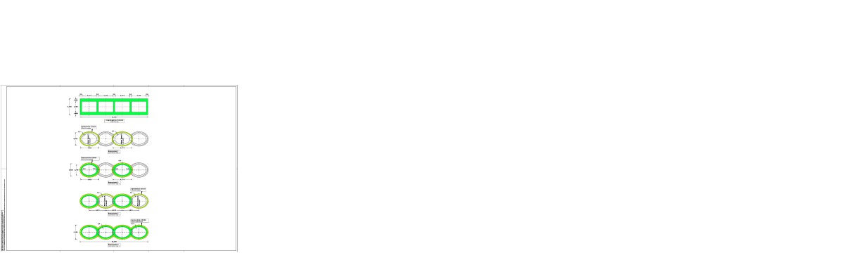
The original design foresaw four rectangular cross-sections, one besides the other, to be built according to the cut-and-cover method (Fig. 5 top). On demand of the joint venture and on the basis of a feasibility study, design was modified such that the vent tunnels could be built according to the mining method. Towards this end, the rectangular cross-sections were replaced by nearly elliptical cross-sections with the same cross-sectional area, which intersect each other (Fig. 5).
The construction pits for the switchbox as well as for the technical building had been built before the tunnel excavation was started. Overlapping bored piles, anchored to the ground above the vent tunnels, were constructed to support the walls of the construction pit for the technical building. The walls of the construction pit for the switch box, on the other side of Al-Diwan Road, were supported by a slurry trench wall anchored with prestressed anchors. The prestressed anchors were replaced by SN-anchors located outside the planned tunnel cross-sections (Figs. 3 and 4).
The ventilation tunnels were excavated by conventional means, with pipe umbrellas. Heading was started from the construction pit of the technical building. An approx. 15 m long, horizontal pipe umbrella was drilled from the construction pit for the switch box. Another pipe umbrella, with an inclination of ~2.4°, was drilled from the construction pit for the technical building. The two pipe umbrellas have an overlap of around 5 m in the central area of the tunnels (Fig. 4).
In a first step, tunnels 1 and 3 were driven and supported with a 30 cm thick shotcrete membrane (Fig. 5). In a second step, the internal lining of reinforced concrete was installed in both tunnels. In a third step, the tunnels 2 and 4 were excavated. In the area of the vault and of the invert, the shotcrete membranes of tunnels 2 and 4 are supported by the shotcrete membranes of tunnels 1 and 3. In the fourth step, the internal lining was installed in tunnels 2 and 4. For connection of these internal linings to the internal linings of the neighbouring tunnel tubes 1 and 3, corresponding block-outs have been foreseen in the latter ones (Figs. 5 + 14).
3 Ground Conditions
The ventilation tunnels are completely located in the so-called Simsima Limestone. On top of this unit, top soil or man-made soil with minor thickness is encountered. Below Simsima Limestone, Midra Shale and Rus Formation are encountered (Fig. 4).
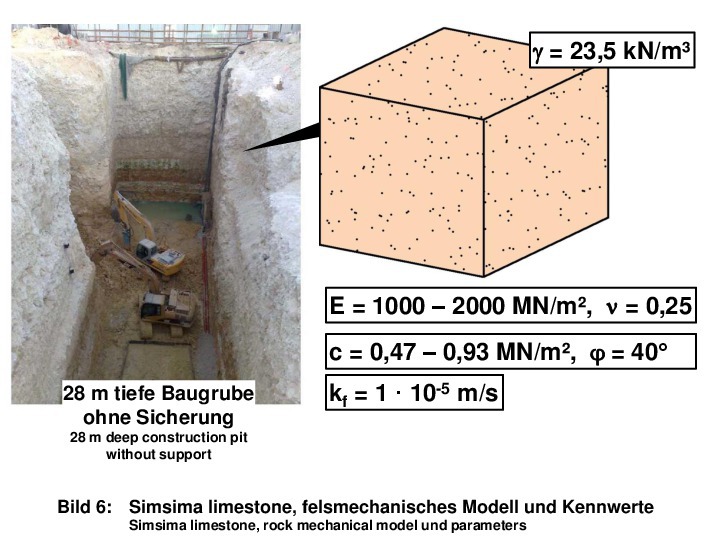
Simsima Limestone is a fine-grained, crystalline limestone. It is partially dolomitic and reveals slight karstification. On a large scale, it can be judged as homogeneous regarding its deformability and strength. Furthermore, as a rule, no joints nor bedding-parallel discontinuities are encountered such that isotropic behavior can be assumed.
Thus, WBI has simulated homogenous and isotropic behavior in the rock mechanical model (Fig. 6). The deformation modulus was derived from test results and amounts to approx. 1000–2000 MN/m². The unconfined compressive strength amounts to approx. 2–4 MN/m².
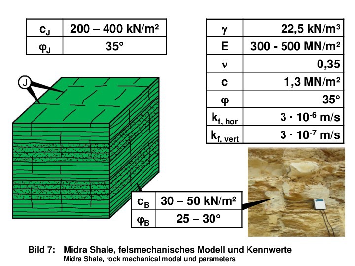
Midra Shale, the geological unit below Simsima Limestone, is encountered beneath the tunnel structures. It consists of an alternating sequence of intensely bedded siltstones and crystalline limestones. Besides the pronounced bedding, steeply inclined joint sets are observed in Midra Shale. The shear strength along these discontinuities is reduced in comparison with the intact rock strength. This results in an anisotropic behaviour of the rock mass. Correspondingly, the rock mechanical model is more complicated and considers the inhomogeneous composition as well as the anisotropy resulting from discontinuities (Fig. 7). Due to the softer siltstone layers, the deformability of Midra Shale is higher than the one of Simsima Limestone. The unconfined compressive strength is in the same order of magnitude as for Simsima Limestone. A reduced shear strength must be assumed along the discontinuities.
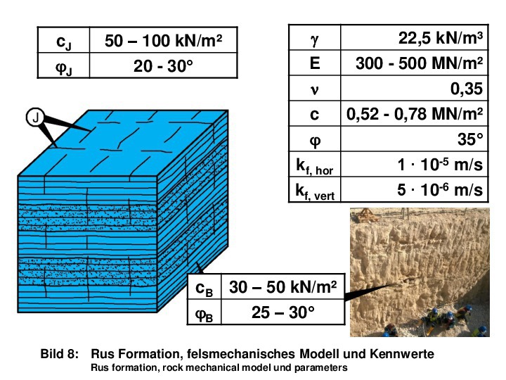
The rock mechanical model and the rock mechanical parameters for the Rus formation, encountered below Midra Shale, is represented in Fig. 8. The discontinuity fabric is similar to the one of Midra Shale. However, the strength of the intact rock as well as along the discontinuities is smaller.
The above described rock mechanical models assume isotropic linear-elastic behavior of the rock mass until strength is reached. This is a slight simplification for Midra Shale and Rus Formation, because the deformability of these formations possibly is slightly larger perpendicularly to bedding than in parallel with bedding. According to the AJRM (Anisotropic Jointed Rock Model), transversely-isotropic behavior could thus be assumed, which is resulting from the lining-up of clay minerals in the intact rock [4]. However, according to experience, the anisotropy of the intact rock in the elastic range can be neglected.
For Midra Shale and Rus formation, the strength along the directions of bedding-parallel discontinuities and of vertical joints is smaller than in other directions. According to the AJRM and the Mohr-Coulomb failure criterion, a cohesion and an angle of friction are introduced.
The tensile strength perpendicular to the discontinuities as well as of the intact rock are assumed zero. The intact rock strength, which in the given case does not have any impact on the results, is also described with the aid of the Mohr-Coulomb parameters c and φ.
After exceeding the strength, viscoplastic behavior is assumed [4].
Thus, differing from other models, the above described AJRM allows to consider a directional strength and thus describes the reality in a better way, leading to more economic solutions.
4 Stability Analyses and Proofs
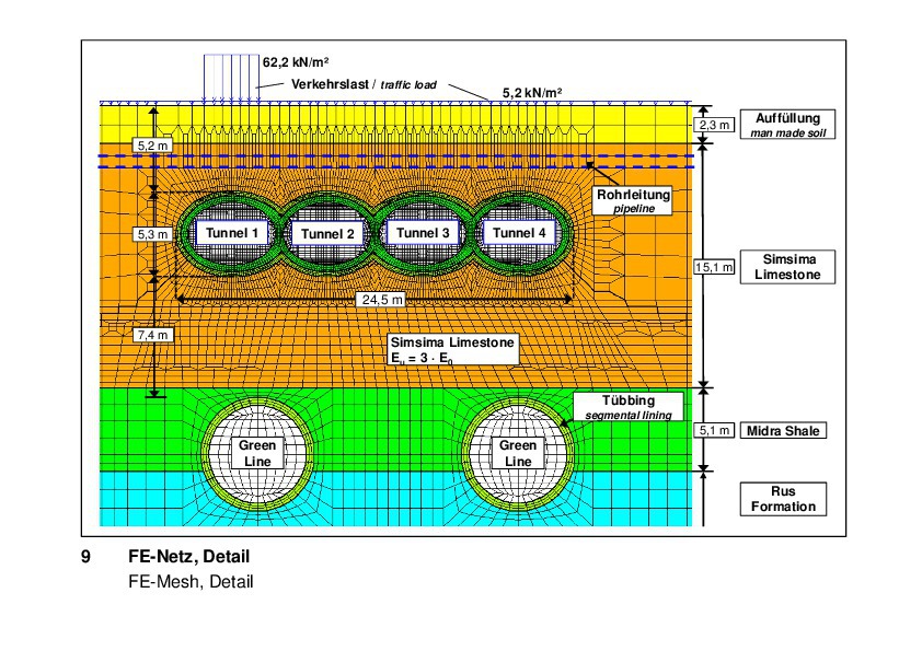
The stability analyses have been carried out according to the finite element method with the program system FEST03. The above described AJRM is integrated in this program system [5]. A vertical slab with 1 m thickness has been considered in the analyses (pseudo 3D). The FE mesh is represented in Fig. 9. It considers
the different geological units as well as the four vent tunnels. The shotcrete membranes and the reinforced concrete linings of the four tunnel tubes have been discretized with three rows of elements. This allows for evaluation of the stress resultants via integration of stresses calculated in the Gauss points of the individual elements.
In the Midra Shale and Rus Formation below the vent tunnels, the two tunnel tubes of the Green Line have been simulated with a circular cross-section. Strictly speaking, they should have been
simulated with an elliptical cross-section, because they are obliquely cut. However, since the two already constructed tunnel tubes do not have a major influence on the stability of the vent tunnels, this simplification is admissible.
In the presented example, the traffic loads have been considered with a uniform load of 5.2 kN/m² and an additional traffic load, which is applied locally along a certain stretch (Fig. 9).
The undisturbed groundwater table is located approx. 2.2 m above the roof of the vent tunnels. It is lowered due to the tunnel heading and will rise to the original level only after installation of the internal lining. For the rock mass located beneath the vent tunnels, a decompression modulus is assumed, which is three times the above mentioned deformation modulus for first loading of the Simsima Limestone.
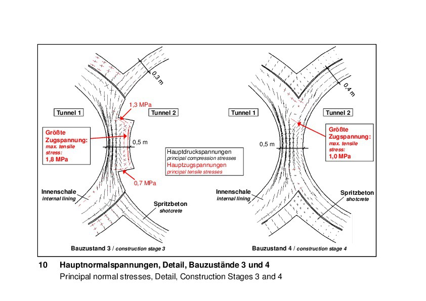
The results of the analyses are not represented in detail in this article. Rather small stresses result in the shotcrete membranes as well as in the internal linings of reinforced concrete. The calculated subsidences at the road surface due to tunnel heading are also small. Peculiarities and higher stresses, respectively, do only result in the area of intersection of neighbouring tunnel tubes and of the connection of the shotcrete membranes of tunnels 2 and 4 to the shotcrete membranes of the neighboring tunnels 1 and 3. Fig. 10 exemplarily shows the principal normal stresses in the reinforced
concrete linings of tunnels 1 and 2 for two different construction
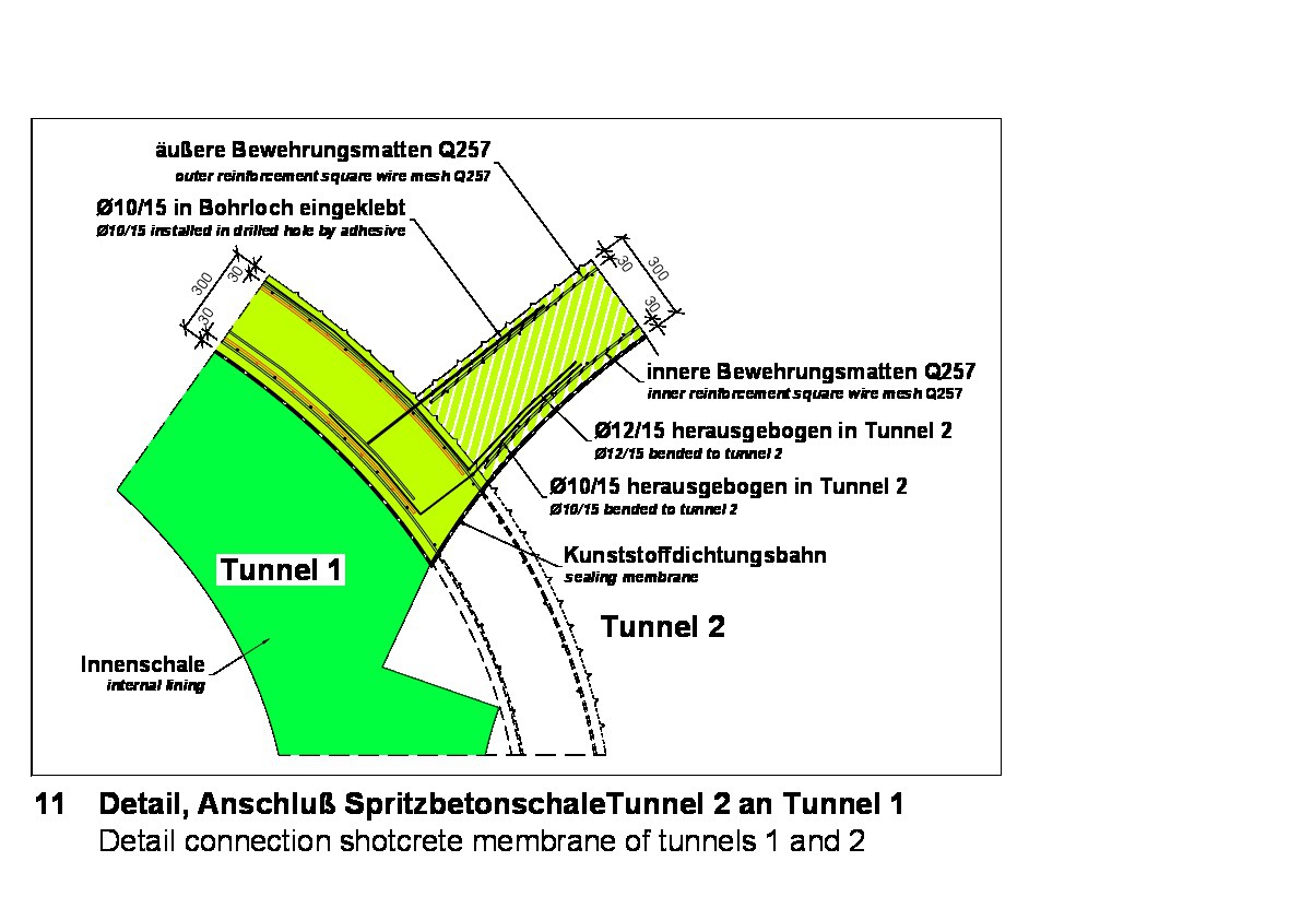
stages (see Fig. 5). Also here, the resulting reinforcement quantities are small. In Fig. 11, a detail of reinforcement location is exemplarily shown for the connection of the shotcrete membranes of tunnels 2 and 4 to the neighbouring tunnel tubes.
5 Construction
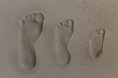
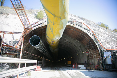
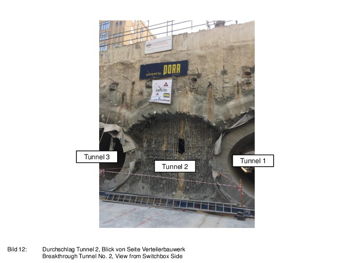
Excavation of the tunnels was carried out according to schedule without any incidences. The subsidence at road surface amounted to a maximum of 17 mm. Fig. 12 shows the construction stage, in which the reinforced concrete internal lining of tunnels 1 and 3 was completed and the tunnel tube inbetween was about to be broken through to the construction pit “switchbox” (see quadratic hole in the center of the cross-section). As can be seen in the photograph, the slurry trench wall had been removed before tunnel heading of tunnel 2 arrived. Also, the pipe umbrella along the tunnel’s roof can be seen in the photograph.
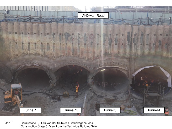
A photograph of construction stage 3 is shown in Fig. 13. Here, the tunnels 2 and 4 are completely excavated. The photograph gives a good impression of the dimensions of the structure as well as of the small height of overburden to Al-Diwan Road.
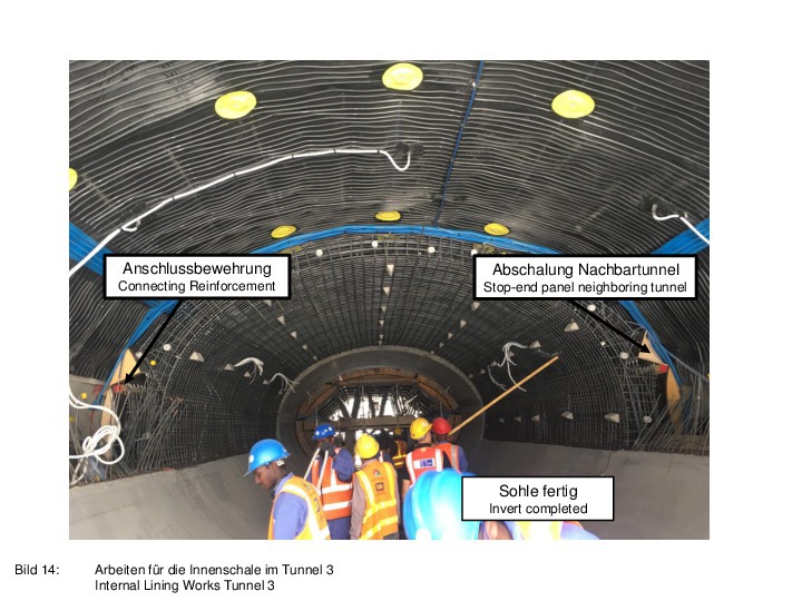
Finally, Fig. 14 exemplarily shows the installation of the internal lining in tunnel 3. The concrete invert is already finished. One can see the formworks (stop-end panels), which have been installed during construction of the internal linings of tunnel tubes 1 and 3 in order to prepare the connection to the reinforced concrete linings of the neighboring tunnel tubes 2 and 4.
6 Summary
In the course of the construction of the Green and Red Lines for the underground network of Qatar, a ventilation structure is built. The technical building is located directly besides Al-Diwan Road. On the opposite side of the road, the switchbox structure is located. This structure connects the ventilation building with the tunnels of the Green and Red Line. The four vent tunnels connecting the technical building with the switchbox structure, had originally been designed as cut-and-cover structures with rectangular cross-section of reinforced concrete. The joint venture of Porr and Redco International asked WBI to elaborate a feasibility study and the detailed design for construction of the vent tunnels below Al-Diwan Road according to the mining method. Instead of the rectangular cross-sections, nearly elliptical cross-sections with equivalent cross-sectional area, which intersect each other, were executed. The tunnels were constructed with conventional means, 30 cm thick shotcrete membranes and internal linings of reinforced concrete. The two pipe umbrellas, which were executed from the two construction pits on either side, have an overlap of 5 m in the center section of the tunnels.
The ground consists of limestones, which in part are horizontally bedded and vertically jointed. The rock mechanical model was elaborated according to the AJRM method. Stability analyses were carried out according to the finite element method with the
program system FEST03. In the given article, construction is briefly dealt with. Construction was completed according to schedule without any incidence. The maximum subsidence at road surface amounted to 1.7 cm.